Showing posts with label Digital Signal Processing. Show all posts

Monday, May 10, 2021

Basics of Fourier Transform

Fourier Transform is a mathematical tool that is widely used in Signal processing applications.

Fourier Transform is explained in this VIDEO in just SIX minutes.

https://youtu.be/Og6JDPxQBFM


Thursday, December 20, 2012

Band Stop Filter

It is also called band-elimination, band-reject, or notch filters which passes all frequencies above and below a particular range set by the component.


Twin-T Band-stop filter

The low-pass filter section is comprised of R1, R2, and C1 in a “T” configuration. The high-pass filter section is comprised of C2, C3, and R3 in a “T” configuration .Hence it is commonly known as a “Twin-T” filter


  • A band-stop filter screens out frequencies with in a certain range and thus provides easy way to frequency  outside that range. Also known as band-elimination, band-reject, or notch filters.
  • It  can be built by placing a low-pass filter in parallel with a high-pass filter. Both the low-pass and high-pass filter sections are of the “T” configuration, giving the name “Twin-T” to the band-stop combination.
  • The frequency of maximum attenuation is called the notch frequency.


  • courtesy:allaboutcircuits.com


    Hardwork Can Never Ever Fails...
    Best Luck...

    Band Pass Filter

    It passes frequency with in the certain range.Circuits can be designed to accomplish this task by combining the properties of low-pass and high-pass into a single filter. The result is a band-pass filter.

    Types:

    1. Capacitive band-pass filter.


    This construction allows the frequency that are neither too high nor too low.The response of a capacitive bandpass filter peaks within a narrow frequency range.

    2.Inductive band-pass filter.

    Band-pass filters can also be constructed using inductors. But, the capacitive band pass filter gives more advantage.

    Here, the high-pass section comes “first” in this design instead of the low-pass section makes no difference in its overall operation. It will still filter out all frequencies too high or too low.


  • A band-pass filter works to screen out frequencies that are too low or too high, giving easy passage only to frequencies within a certain range.
  • Band-pass filters are built by stacking a low-pass filter on the end of a high-pass filter, or vice versa.


  • courtesy:allaboutcircuits.com


    Hardwork Can Never Ever Fails...
    Best Luck...

    High Pass Filter

    A high-pass filter performs  the opposite function  of a low-pass filter.It offer easy passage of a high-frequency signal and difficult passage to a low-frequency signal.

    TYPES:


    1.Capacitive high-pass filter.


    The capacitor's impedance increases with decreasing frequency. This high impedance in series leads to block  the low-frequency signals from getting to load.
    The response of the capacitive high-pass filter increases with frequency.

    2.Inductive high-pass filter.


    The inductor's impedance decreases with decreasing frequency. This low impedance in parallel tends to short out low-frequency signals from getting to the load resistor. As a result, most of the voltage gets dropped across series resistor R1.
    The response of the inductive high-pass filter increases with frequency.

    By Conclusion,
    The capacitive design is the simplest since it requires only one component above and below the load.And, again, the reactive purity of capacitors over inductors tends to favor their use in filter design, especially with high-pass filters where high frequencies commonly cause inductors to behave strangely due to the skin effect and electromagnetic core losses.

    Example:


    courtesy:allaboutcircuits.com


    Hardwork Can Never Ever Fails...
    Best Luck...

    Wednesday, December 19, 2012

    Low Pass Filter

    A low-pass filter is a circuit that allows low-frequency very easily and does not allows high-frequency easily. There are two basic kinds of circuits

    1.Capacitive low-pass filter


    The capacitor's impedance decreases with increasing frequency. This low impedance in parallel with the load resistance tends to short out high-frequency signals.It drops most of the voltage across series resistor R1


    The response of a capacitive low-pass filter falls off with increasing frequency.

    2.Inductive low-pass filter


    The inductor's impedance increases with increasing frequency. This high impedance in series tends to block high-frequency signals from getting to the load.

    The response of an inductive low-pass filter falls off with increasing frequency.


    By Conclusion,

    In this case,the  inductive low-pass filter is very simple in structure. The capacitive version of this filter is not that much more complex, with only a resistor and capacitor needed for operation. Due to its complexity, capacitive filter designs are generally preferred over inductive because capacitors tend to be “purer” reactive components than inductors and therefore are more predictable in their behavior. By “pure” I mean that capacitors exhibit little resistive effects than inductors, making them almost 100% reactive. Inductors, on the other hand, typically exhibit significant dissipative (resistor-like) effects, both in the long lengths of wire used to make them, and in the magnetic losses of the core material. Capacitors also tend to participate less in “coupling” effects with other components than inductors, and are less expensive.


    courtesy:allaboutcircuits.com


    Hardwork Can Never Ever Fails...
    Best Luck...

    what is filter?

    Sometimes, Some kind of operations requires certain range of frequencies to perform its operation more efficiently.Thus a circuit is designed to perform such operation is called filter circuit.It is mostly needed in stereo systems,where certain range of audio frequency is required to be amplified.Also equalizers are used that allow the amplitude of several  frequency ranges to be adjusted to suit the listener's taste and acoustic properties of the listening area.Another one,Cross network which block certain ranges of frequencies from reaching speakers.                     

    A tweeter (high-frequency speaker) is inefficient at reproducing low-frequency signals such as drum beats, so a crossover circuit is connected between the tweeter and the stereo's output terminals to block low-frequency signals, only passing high-frequency signals to the speaker's connection terminals. This gives better audio system efficiency and thus better performance. Both equalizers and crossover networks are examples of filters, designed to accomplish filtering of certain frequencies.

    Practical Application:

    Conditioning of non-sinusoidal voltage waveforms in POWER CIRCUIT.
    some devices are sensitive to the harmonics in the power supply and hence requires power conditioning.
    If there is a harmonics in the power supply,then the filter can be constructed that allows only the fundamental frequency by blocking the harmonics.


    courtesy:allaboutcircuits.com


    Hardwork Can Never Ever Fails....
    Best Luck...

    Friday, August 24, 2012

    Why we go for Digital?


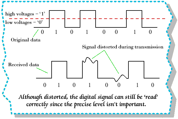
    • One advantage of digital circuits when compared to analog circuits is that signals represented digitally can be transmitted without degradation due to noise. For example, a continuous audio signal, transmitted as a sequence of 1s and 0s, can be reconstructed without error provided the noise picked up in transmission is not enough to prevent identification of the 1s and 0s. An hour of music can be stored on a compact disc as about 6 billion binary digits.

    • In a digital system, a more precise representation of a signal can be obtained by using more binary digits to represent it. While this requires more digital circuits to process the signals, each digit is handled by the same kind of hardware. In an analog system, additional resolution requires fundamental improvements in the linearity and noise characteristics of each step of the signal chain.
    • Computer-controlled digital systems can be controlled by software, allowing new functions to be added without changing hardware. Often this can be done outside of the factory by updating the product's software. So, the product's design errors can be corrected after the product is in a customer's hands.
    • Information storage can be easier in digital systems than in analog ones. The noise-immunity of digital systems permits data to be stored and retrieved without degradation. In an analog system, noise from aging and wear degrade the information stored. In a digital system, as long as the total noise is below a certain level, the information can be recovered perfectly.

    Finally one question to the readers

    Is reality digital or analog?

    What are Digital Signal Processors?

    Digital Signal Processors (DSPs) take real-world signals like voice, audio, video, temperature, pressure, or position that have been digitized and then mathematically manipulate them. 

    A DSP is designed for performing mathematical functions like "add", "subtract", "multiply" and "divide" very quickly.

    Signals need to be processed so that the information that they contain can be displayed, analyzed, or converted to another type of signal that may be of use. 

    In the real-world, analog products detect signals such as sound, light, temperature or pressure and manipulate them. Converters such as an Analog-to-Digital converter then take the real-world signal and turn it into the digital format of 1's and 0's. 

    From here, the DSP takes over by capturing the digitized information and processing it. It then feeds the digitized information back for use in the real world. It does this in one of two ways, either digitally or in an analog format by going through a Digital-to-Analog converter. All of this occurs at very high speeds.

    DSP in MP3 Audio Player


    To illustrate this concept, the diagram above shows how a DSP is used in an MP3 audio player. 

    During the recording phase, analog audio is input through a receiver or other source. This analog signal is then converted to a digital signal by an analog-to-digital converter and passed to the DSP. 

    The DSP performs the MP3 encoding and saves the file to memory. During the playback phase, the file is taken from memory, decoded by the DSP and then converted back to an analog signal through the digital-to-analog converter so it can be output through the speaker system. 

    (Courtesy: www.analog.com)

    Monday, August 13, 2012

    What is Clock Skew and Jitter?

    Click Skew and Jitter
    Consider the drawing above. The green trace (and equation) represents the ideal case (a pure sine tone at the exact frequency desired with zero crossings at the exact locations desired, therefore sigma = 0). 

    The blue trace represents an exact replica of the green trace, except that the zero crossings are delayed with respect to the green trace (therefore phi = a constant). 

    The blue trace is said to have skew (i.e. a fixed delay) with respect to the green trace. 

    Now consider the red trace. It too has a skew component relative to the green trace; but not to the same degree as the blue trace. However, the points at which the red trace crosses the x-axis vary with time. The value of phi is a function that contains both a constant (which explains the fixed skew) and a random function, usually noise that is associated with gaussian processes or even deterministic noise sources.

    The green trace is the most desirable since it is exactly what our system needs in terms of frequency, delay, and noise. 

    The least desirable trace is the red trace. 

    Why wouldn't the blue trace be least desirable? Because a fixed delay (skew) is usually correctable using software, board layout techniques, etc However, removing the noise on the red trace is considerably more complicated.

    The characteristic of the periodicity of a signal varying with time in a random, undesirable fashion is called Jitter. 

    Jitter comprises two components: 

    • bounded (or deterministic) jitter, and 

    • unbounded (or random) jitter. 

    Deterministic jitter exhibits behavior that is predictable and repeatable; therefore it can be quantified accurately with a relatively low number of observations. For this reason, deterministic jitter can be expressed as a peak to peak value (a typical value might be 5 ps pk-pk). 

    On the other hand, random jitter is the result of uncorrelated stochastic processes which makes it much less straightforward to measure or quantify. Random jitter is expressed as an RMS value and requires that a measurement bandwidth be appended to it as a qualifier. A typical value for random jitter might be 1 ps RMS (12 kHz - 20 MHz).

    Jitter family tree