
Showing posts with label Electrical Basics. Show all posts
Showing posts with label Electrical Basics. Show all posts
Thursday, October 09, 2014
Wednesday, December 19, 2012
DC AND AC CURRENT IN ELECTRIC FIELD
Differences between alternating currents (AC) and direct currents (DC). You can read a brief synopsis of these two electrical systems and then begin your exploration of these inventions by clicking on either AC or DC in the electrical system interactive. By clicking on AC, DC, wire, battery, AC generator, or light bulb you will learn about alternating and direct currents, what exactly an electric current is, and two ways that the currents can be produced.
Alternating Current (AC)
Alternating current (AC) electricity is the type of electricity commonly used in homes and businesses throughout the world. While direct current (DC) electricity flows in one direction through a wire, AC electricity alternates its direction in a back-and-forth motion. The direction alternates between 50 and 60 times per second, depending on the electrical system of the country.
AC electricity is created by an AC electric generator, which determines the frequency. What is special about AC electricity is that the voltage can be readily changed, thus making it more suitable for long-distance transmission than DC electricity. But also, AC can employ capacitors and inductors in electronic circuitry, allowing for a wide range of applications.
Direct Current (DC) Electricity.
Direct current or DC electricity is the continuous movement of electrons from an area of negative (−) charges to an area of positive (+) charges through a conducting material such as a metal wire. Whereas static electricity sparks consist of the sudden movement of electrons from a negative to positive surface, DC electricity is the continuous movement of the electrons through a wire.
A DC circuit is necessary to allow the current or steam of electrons to flow. Such a circuit consists of a source of electrical energy (such as a battery) and a conducting wire running from the positive end of the source to the negative terminal. Electrical devices may be included in the circuit. DC electricity in a circuit consists of voltage, current and resistance. The flow of DC electricity is similar to the flow of water through a hose.
Difference between AC and DC electricity
Electrons have negative (−) electrical charges. Since opposite charges attract, they will move toward an area consisting of positive (+) charges. This movement is made easier in an electrical conductor, such as a metal wire.
Electrons move direct with DC electricity
With DC electricity, connecting a wire from the negative (−) terminal of a battery to the positive (+) terminal will cause the negative charged electrons to rush through the wire toward the positive charged side. The same thing happens with a DC generator, where the motion of coiled wire through a magnetic field pushes electrons out of one terminal and attracts electrons to the other terminal.
Electrons alternate directions in AC electricity
With an AC generator, a slightly different configuration alternates the push and pull of each generator terminal. Thus the electricity in the wire moves in one direction for a short while and then reverses its direction when the generator armature is in a different position.
AC movement of electrons in wire
The charge at the ends of the wire alternates between negative (−) and positive (+). If the charge is negative (−), that pushes the negatively charged electrons away from that terminal. If the charge is positive (+), the electrons are attracted in that direction.
Rate of change
AC electricity alternates back-and-forth in direction 50 or 60 times per second, according to the electrical system in the country. This is called the frequency and is designated as either 50 Hertz (50Hz) or 60 Hertz (60Hz).
Light bulbs in Both AC and DC
Many electrical devices—like light bulbs—only require that the electrons move. They don't care if the electrons flow through the wire or simply move back-and-forth. Thus a light bulb can be used with either AC or DC electricity.
Monday, December 17, 2012
DC and AC Electric motors
DC motors
A simple DC motor has a coil of wire that can rotate in a magnetic field. The current in the coil is supplied via two brushes that make moving contact with a split ring. The coil lies in a steady magnetic field. The forces exerted on the current-carrying wires create a torque on the coil.
AC motors
With AC currents, we can reverse field directions without having to use brushes. This is good news, because we can avoid the arcing, the ozone production and the ohmic loss of energy that brushes can entail. Further, because brushes make contact between moving surfaces, they wear out.
The first thing to do in an AC motor is to create a rotating field. 'Ordinary' AC from a 2 or 3 pin socket is single phase AC--it has a single sinusoidal potential difference generated between only two wires--the active and neutral. (Note that the Earth wire doesn't carry a current except in the event of electrical faults.) With single phase AC, one can produce a rotating field by generating two currents that are out of phase using for example a capacitor. In the example shown, the two currents are 90° out of phase, so the vertical component of the magnetic field is sinusoidal, while the horizontal is cosusoidal, as shown. This gives a field rotating counterclockwise
From simple AC theory, neither coils nor capacitors have the voltage in phase with the current. In a capacitor, the voltage is a maximum when the charge has finished flowing onto the capacitor, and is about to start flowing off. Thus the voltage is behind the current. In a purely inductive coil, the voltage drop is greatest when the current is changing most rapidly, which is also when the current is zero. The voltage (drop) is ahead of the current. In motor coils, the phase angle is rather less than 90 degee, because electrical energy is being converted to mechanical energy.
Thursday, November 29, 2012
How light bulb glows?
An LED lamp uses light emitting diode as the source which comes under solid state devices.It offers long life and energy efficiency with low cost than those of fluorescent and incandescent lamps.

The
chassis of the bulb is made of ceramic and houses the electronic
ballast. Ceramic is used for its insulating and heat dissipative
properties. The LED bulb is housed inside a phosphor coated glass dome.Remote phosphor is used to provide constant wavelength and enhance light output. This also
enables the LED to emit only a single colored light throughout its lifetime
while also reducing glare at the same time.

Courtesy:engineersgarage.com
Hardwork Can Never Ever Fails...
Best Luck...
Tubelight starter-working
Nowadays, fluorescent lights are mostly used lighting system.It is being filled with mercury vapor.Electric charges are used to excite mercury atoms to provide ultraviolet light.starter is used in the tube light circuit to provide an initial current to filaments of the tube light.Look below to understand the purpose of starter.

Current will not pass in to the circuit as soon as the switch is pressed because the gas inside it is not ionized and the tube light behaves a open circuit. Once the gas is ionized, it will provide a conduction path for the current to flow.Hence to ionize,an initial high is required for a short period of time across the filament of the main tube.This work is being done by a starter.
By conclusion,
To make the tube light to be ON ,it must be ionized using the starter current.
By conclusion,
To make the tube light to be ON ,it must be ionized using the starter current.
Courtesy:engineersgarage.com
Hardwork Can Never Ever Fails..
Best Luck...
Wednesday, October 10, 2012
What is War of Currents?
Why mostly the Power Distribution systems uses AC over DC?
Actually, at the time of development in Electrical Systems and Electrical Distribution, Both AC and DC were used for the Power Distribution.
 |
| AC Generator |
Thomas Edison Promoted DC Power Distribution System and Nikola Tesla and George Westinghouse, promoted the AC Power Distribution System.
This is known as War of currents! (1880s)
Finally AC won over the DC Power Distribution System.
The main Reasons for use of AC in Power Distribution System are:
1. When Electricity passes through a Conductor, there is Transmission loss in the form of Heat. It is also known as Ohmic Loss.
Power Loss = I^2 Rt
Where I = Current
R = Resistance of the Conductor
t = time
So if we transmit larger currents, the loss will be more.
However, in AC, there is a relation for the Transformers
I1V1=I2V2
ie, when the Voltage at one end of the transformed increases, Current decreases.
This is because, we have to keep the product of Current and Voltage constant.
So if we can transmit the Current at Higher Voltage, it will reduce the current through the Conductor and in effect the Ohmic Power loss will decrease.
2. Long distance Power Transmission is possible with Higher voltage. This can be easily achieved using the Transformers in AC, However Stepping up and Stepping Down using Transformers are not possible in DC.
 |
| AC Power Distribution |
However there are some advantages for DC over AC
DC power maintains a constant direction of current. One advantage of DC power is there is no reactance in the line.
This allows higher power transfer capability, higher capacity utilization of generators, and less of a voltage drop along the line.
DC also has a lower line resistance than AC because of the “skin effect” in AC. This is when charge is carried mostly near the outside of the wire.
In the DC system, power is just the real component. This means that the transmission system operator need not worry about the sufficiency of reactive power to maintain the security and stability of the system.
In DC, there is no frequency, so generators connected to the transmission grid do not need to be synchronized.
The DC system does not introduce susceptance along the line thus removing the effect of changing current and over voltages in the system.
Analysis of DC systems only involves real numbers, while AC systems involve complex numbers. (Think about a world without AC; How easy will be the calculations in Electrical Engineering :-) )
A good Resource for studying the AC Theory is available Here
Friday, September 14, 2012
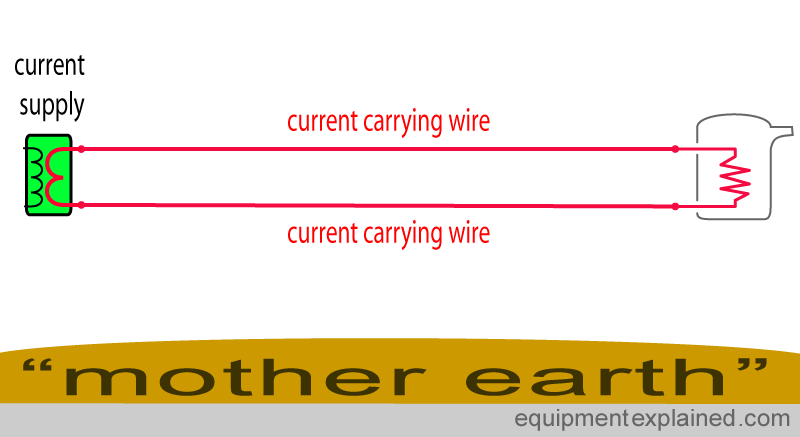
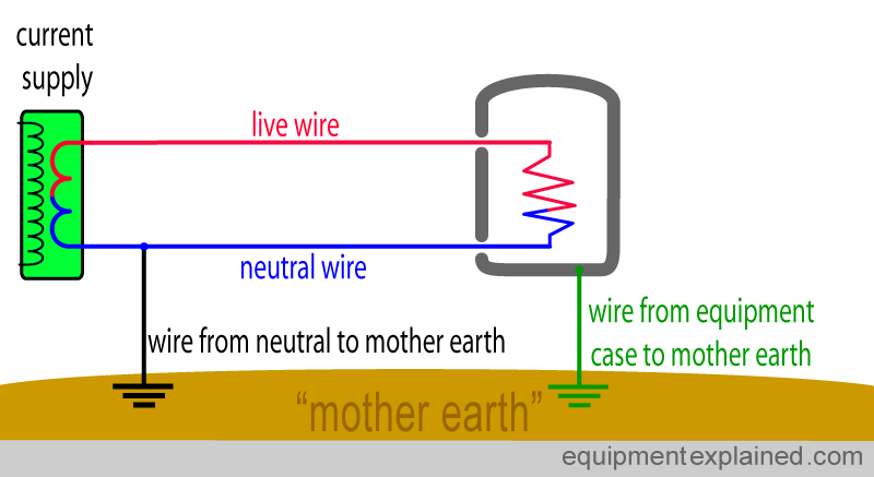
What is Phase, Neutral and Earth?
1. load current flows through neutral, but in normal operation, no load current will ever flow through earth (In some countries it is also called Ground, but usually Ground is related to DC).
2. It can be stated that Neutral can be grounded, but Ground is not neutral.
3. From the Generation side, the Neutral and Earth have the same common point.
4. Neutral/Earth in this case would act as the return path of the supply.
5. From the Distribution side, we start to run the Neutral lines.
6. Neutral in this case would be the return path of the supply.
7. Earth is still available but normally there will be no current flowing, only during supply leakage.
In Home, neutral is the return path of the current to the transformer and Earthing is for avoiding the shock.
However in Distribution side both have the same meaning and using as the return path of the current. ie, they are using the Earth as the return path of electricity rather than using a Separate wire.
The below images explains the concepts well.
If you want to study more about the same, please visit this Blog.
He has explained this concept with his own illustrations and explained in a simple manner.


(Image Courtesy: www.equipmentexplained.com)
Sunday, August 12, 2012
BASIC ELECTRICITY
ATOMS AND MOLECULES:
ATOMS
As we know, everything in the world, whether solid, liquid, or gas, is made up of atoms. Each atom contains some number of electrons, protons, neutrons, and other sub-atomic stuff. The nucleus (central region) of each atom contains the protons (positive charge) and neutrons (no charge). Electrons (negative charge) live in a cloud around the outside. Since electrons and protons are charged particles, each atom prefers to have the same number of electrons as protons.

MOLECULES
Atoms of one or more types are organized into molecules. There are only a hundred or so types of atoms, but there are an almost infinite number of different molecules. Molecules are the building blocks from which all real objects are made.

Molecules are not always so simple. Some organic molecules (like those in our bodies) can comprise hundreds of atoms.
Every atom has its own complement of electrons. In a conductor, some of those electrons can jump from atom to atom. But electrons don't move from atom to atom without a reason. When electrons are flowing there is always an electrical force pushing them along. We called this force as "Voltage".
Current In very simple terms, current is the flow rate of the electrons in the circuit.
Are Voltage and Current Related?
Voltage and current are not the same thing, although they are closely related. In simple terms, Voltage causes Current. Given a Voltage and a path for the electrons, current will flow. Given the path, but no Voltage, or Voltage without the path, there will be no current.

This picture illustrates a single cell pocket flashlight. The 1.5 Volt cell is pushing the electrons through the bulb and the wire. Without this push, the electrons would be happy to remain stationary. In this case, chemical action within the battery causes the push. When the battery gets old, its chemical reaction slows down and its internal push gets weaker and weaker.
ELECTRICITY MAGNETISM
MAGNETISM
There are several relationships between electricity and magnetism. We will explore them one by one. The first relationship we will discuss is how current flowing through a wire creates a magnetic field. A steady current creates a steady magnetic field like that created by a magnet.
Electro-Magnet
We can create an electro-magnet by wrapping many turns of wire on a core, then causing an electrical current to flow through this coil of wire. With such a device we can create a magnetic field that can be controlled; we can turn it on and off by controlling the current. In fact, by controlling the current gradually, instead of just on and off as shown here, we could make the magnetic field gradually become stronger or weaker.

The strength of the field is proportional to the amount of current flowing and to the number of turns on the coil. Each turn of wire on the coil contributes to the strength of the magnetic field. If we double the number of turns, we can make an electro-magnet twice as strong. But, this exact ratio is only true if the current flow is the same for both coils.
There are several relationships between electricity and magnetism. We will explore them one by one. The first relationship we will discuss is how current flowing through a wire creates a magnetic field. A steady current creates a steady magnetic field like that created by a magnet.
Electro-Magnet
We can create an electro-magnet by wrapping many turns of wire on a core, then causing an electrical current to flow through this coil of wire. With such a device we can create a magnetic field that can be controlled; we can turn it on and off by controlling the current. In fact, by controlling the current gradually, instead of just on and off as shown here, we could make the magnetic field gradually become stronger or weaker.
In the animation, we are controlling the current by connecting and disconnecting the battery. When the battery is not connected, there is no current flow, and therefore no magnetic field. When the battery is connected, current flows through the coil, and a magnetic field is created, as shown by the red lines.
In the above animation, the magnetic field curves around from one end of the coil to the other. The field is strongest at the ends of the coil, and gets weaker as we get farther away. The two ends of the coil is called as the "poles". In magnet, one end is "North" pole and the other end is "South" pole.
The strength of the field is proportional to the amount of current flowing and to the number of turns on the coil. Each turn of wire on the coil contributes to the strength of the magnetic field. If we double the number of turns, we can make an electro-magnet twice as strong. But, this exact ratio is only true if the current flow is the same for both coils.
Friday, August 10, 2012
What do you meant by earthing?
Earthing is a safety device used to prevent a shock due to leakages arising from weak insulation, breaking of the element or otherwise.
The metal bodies of appliances handled like the electric iron, kettle or refrigerator must be earthed, that is, connected to a pipe leading deep into the earth on to a metal plate.
In case the metal body becomes live, the circuit is completed through the live wire and the earth, resulting in a high current. The fuse on the live-wire side should blow out immediately, and the matter should be investigated and the fault rectified.
In case the fuse does not blow out, and a person touches it, a severe shock is still prevented. This is because most of the current flows directly to the earth via the earth connection which has negligible resistance.
An extremely small current, if at all, may pass through the person’s body which offers a resistance, resulting in only a mild shock.
For an earth connection, a three-pin socket and plug are required. Due to the high current it draws, the earth pin is made thicker and larger than the other two pins.
This ensures that the plug fits firmly into the socket, reducing the chances of sparking. The heat caused by sparking causes the terminals to wear off and damages the socket and the plug. Because it is larger, the earth connection is made first acting as a safety device.
The metal bodies of appliances handled like the electric iron, kettle or refrigerator must be earthed, that is, connected to a pipe leading deep into the earth on to a metal plate.
In case the metal body becomes live, the circuit is completed through the live wire and the earth, resulting in a high current. The fuse on the live-wire side should blow out immediately, and the matter should be investigated and the fault rectified.
In case the fuse does not blow out, and a person touches it, a severe shock is still prevented. This is because most of the current flows directly to the earth via the earth connection which has negligible resistance.
 |
| 3pin plug |
An extremely small current, if at all, may pass through the person’s body which offers a resistance, resulting in only a mild shock.
For an earth connection, a three-pin socket and plug are required. Due to the high current it draws, the earth pin is made thicker and larger than the other two pins.
This ensures that the plug fits firmly into the socket, reducing the chances of sparking. The heat caused by sparking causes the terminals to wear off and damages the socket and the plug. Because it is larger, the earth connection is made first acting as a safety device.
 |
| Equipment Earthing wire connected |
 |
| Equipment without Earthing wire- Current flows through the users body |
 |
| Equipment with Earthing- Current has two paths; through the users body or the Earth wire |
 |
| Resistance of the Human body is more than that of the Earth wire |
 |
| Earthing saved the life of a person |
Why, when birds sit on transmission lines or current wires doesn't get shock?
Its true that if birds touch the single one line (phase or neutral) they don't get electrical shock... if birds touch 2 lines then the circuit is closed and they get electrical shock..
so if a human touch single one line(phase) then he doesn't get shock if he is in the air (not touching or standing on the ground).
if he is standing on the ground then touching the line (phase) he will get a shock because the ground on what we standing is like line (ground bed - like neutral)। and in the most of electric lines the neutral is grounded..so that means that human who touch the line closes the circuit between phase and neutral.
  |
| birds sitting on the single tranmission line |
Why transformer ratings are in KVA?

Since the power factor of transformer is dependent on load we only define VA rating and does not include power factor .
In case of motors, power factor depend on construction and hence rating of motors is in KWatts and include power factor.
What is difference between fuse and breaker?
 |
| Circuit Braker |
- Fuses are burned at the time of over current flows in the circuit but breakers are just open(not burn) at the time of over current flow.
- Fuses are used in only one time, but breakers are used by multiple number of time
Why electricity in India is in the multiples of 11 like 11kv, 22kv, 33kv ?

Transformer Induced voltage equation contains 4.44 factor.
E=4.44*f*T*phi
E -Induced emf per phase
T -number of turns
f -frequency
phi -maximum flux per pole
From the equation we see that E is proportional to 4.4 and it is in turn multiple of 11.So always transmission voltage is multiple of 11.
Why DC series motor should be started with load?
In any DC motor, the speed of the motor is inversely propotional to the flux and directly proportional to Back EMF .
When starting a series motor the current flowing will be high, but the flux that the motor produces will be moderate since the series winding has less number of turns.
Hence, if u start the motor without load the speed will increase.
As speed increases the back emf increases.
This decreases the current through the series winding and hence flux decreases and the speed further increases.
Theoretically speaking the speed becomes infinite. But practically the motor will accelerate to very high speed , which will damage the motor.
But if you start the motor with the load, you are actually reducing the starting speed hence the motor runs safely.
Since series motors has this property it is used in trains to pull high load.
 |
| circuit diagram of dc series motor |
Can we give DC supply to a Transformer?
 |
| What is inside a Transformer? |
Thursday, August 09, 2012
Can an Electrical Equipment Be Run On Lower/Higher Than Rated Frequency?
 |
| Electric Motor Working |
But can we run a motor rated for 50 Hz on a 60 Hz supply, or vice versa?
The relation between the speed of the motor and its frequency is given by the expression
N = 120f/P.
From this expression, it is evident that the speed of the motor is directly proportional to the supply frequency. Thus any decrease or increase in frequency will affect the speed of the motor.
The relation between the speed of the motor and its frequency is given by the expression
N = 120f/P.
From this expression, it is evident that the speed of the motor is directly proportional to the supply frequency. Thus any decrease or increase in frequency will affect the speed of the motor.
Let us now analyze what exactly happens when a motor of 50Hz made to run with 60Hz supply and vice-versa.
Analysis 1:
When a 50 Hz motor is made to run on 60 Hz supply:
It is general practice in several countries to have all house-hold items and equipments rated for 50 Hz supply. So when such small domestic devices are connected to a 60 Hz supply, they cause a severe problem. For better understanding, let us visualize this small calculation:
[(60Hz – 50 Hz)/ 50 Hz] * 100 = 20 %.
Thus all such equipments run 20 % faster than their normal rated speed.
This is not safe for the equipment as the insulations may be rated for lesser capacity and windings may burn-out.
To run safely, we either require a reduction gear or an expensive 50 Hz source.
Also this 50 Hz motor will operate perfectly on a 60 Hz supply provided its supply voltage is stepped-up.
60 Hz/ 50 Hz = 6/5 * 100 = 120 %.
Analysis 2:
60 Hz motor connected to 50 Hz supply:
It is same as the above, but instead of stepping-up the supply voltage, it is necessary to step-down the supply voltage.
50Hz/ 60 Hz = 5/6 * 100 = 80 %.
Saturday, August 04, 2012
Two bulbs are connected in series but different ratings
Two lamps A and B are rated 60W 220V and 100W 220V respectively
Lamp A by itself has power of P = I x V ; 60=I x 220 ; so I = 60/220 = 0.27 amperes.
Thus the lamp has a resistance V = I x R ; R=220/0.27 = 807 ohms.
Lamp B by itself has a power of P = I x V ; so I = 100/220 = 0.45 amperes.
Thus the lamp has a resistance V=I x R ; R=220/0.45 = 489 ohms.
Since the resistance in series is added up, the total resistance is 807+489 =1296 ohms and the current
I = V/R = 220/1296 = 0.17 Ampere
Since P= I x I x R
For 60W lamp A, P = 0.17 x 0.17 x 807 = 23.3 watts.
For 100W lamp B, P = 0.17 x 0.17 x 489 = 14.1 watts.
So, when they are wired in series, the bright one and the dim one appear to be reversed as to their respective "normal rated powers".
 |
| Two Bulbs in Series |
Lamp A by itself has power of P = I x V ; 60=I x 220 ; so I = 60/220 = 0.27 amperes.
Thus the lamp has a resistance V = I x R ; R=220/0.27 = 807 ohms.
Lamp B by itself has a power of P = I x V ; so I = 100/220 = 0.45 amperes.
Thus the lamp has a resistance V=I x R ; R=220/0.45 = 489 ohms.
Since the resistance in series is added up, the total resistance is 807+489 =1296 ohms and the current
I = V/R = 220/1296 = 0.17 Ampere
Since P= I x I x R
For 60W lamp A, P = 0.17 x 0.17 x 807 = 23.3 watts.
For 100W lamp B, P = 0.17 x 0.17 x 489 = 14.1 watts.
So, when they are wired in series, the bright one and the dim one appear to be reversed as to their respective "normal rated powers".
Why we are having 1phase,2phase & 3phase only and not others?
The total power of the system increases if we increase the number of phases.
Two phase system has 40% power more than single phase system.
Three phase system has 50% power more than two phase system.
But in four phase system it is 7% power only.
Also the design of the system will be more complicated. So we have three phase system only
Wednesday, August 01, 2012
How 3 Phase Power Supply works?
 |
| 3 Phase current flow |
In a three-phase system, three circuit conductors carry three alternating currents (of the same frequency) which reach their instantaneous peak values at different times. Taking one conductor as the reference, the other two currents are delayed in time by one-third and two-thirds of one cycle of the electric current. This delay between phases has the effect of giving constant power transfer over each cycle of the current and also makes it possible to produce a rotating magnetic field in an electric motor.
Subscribe to:
Posts (Atom)