Sunday, July 22, 2012

2D Convolution in Image Processing-Animation

2D Convolution (image processing):

-An image processing operation that is used to spatially filter an image. 
-A convolution is defined by a kernel that is a small matrix of fixed numbers (coefficients). 
-The size of the kernel, the numbers within it, and a single normalizer value define the operation that is applied to the image. 
-The kernel is applied to the image by placing the kernel over the image to be convolved and sliding it around to center it over every pixel in the original image. At each placement the numbers (pixel values) from the original image are multiplied by the kernel number that is currently aligned above it. 
-The sum of all these products is tabulated and divided by the kernel's normalizer. This result is placed into the new image at the position of the kernel's center. The kernel is translated to the next pixel position and the process repeats until all image pixels have been processed. 
-As an example, a 3x3 kernel holding all 1's with a normalizer of 9 performs a neighborhood averaging operation. Each pixel in the new image is the average of its 9 neighbors from the original.  
                                    
                                           2D Convolution on single Pixel, using 3 X 3 Kernel
                                              3x3 kernel requires 9 passes: normalizer = 9. 

  
-In a raster type image, only one Kernel coefficient operates during a single pass; after 9 passes, all 3x3 coefficients will have operated on the image. 


Hardwork Can Never Ever Fails....
Best Luck....

Saturday, July 21, 2012

Vertical Antenna-Animation

Vertical antenna:

    First antenna is a 1/4 wavelength Vertical Dipole
    Second antenna is a 1/2 wavelength Vertical Dipole (Collinear Array)
  1) a vertical antenna is omni-directional;
  2) the ground plane (reflection) creates virtual elements;
  3) and the effect of adding more elements (Collinear Array) on
     directional gain. --Less sky & ground waves.  

 As the second dipole is introduced, note the Flattening of the pattern, this is effectively doubling the Antenna Gain, i.e., reducing the skywave and groundwaves.

Hardwork Can Never Ever Fails...
Best Luck..


Positive and Negative logic gates-Animation

Positive and Negative Logic gates:

Hardwork Can Never Ever Fails...
Best Luck...

Capacitor and its application- Explanation & Animation


What is Capacitor?

A capacitor is a passive electronic component that stores energy in the form of an electrostatic field.  In its simplest form, a capacitor consists of two conducting plates separated by an insulating material called the dielectric.  Capacitance is directly proportional to the surface areas of the plates, and is inversely proportional to the plates' separation. 

  Applications:

  Some of the applications are given below:

                                                           A.C. & D.C. Coupling 
                                             Notice  Differentiation in the A.C. channel

                                                          Capacitor as a Coupling Element


R.C. & D.C. Coupling 
Notice  Integration in the R.C. channel
Capacitor as a Filtering Element


 Capacitors as Power Supply "Bypassing" ElementsCap


Hardwork can Never Ever fails... 
Best Luck....
Capacitor


JFET,MOSFET biasing-Explanatin and Animation

JFET

What if JFET?

In the junction FET (JFET), the gate material is made of the opposite polarity semiconductor to the channel material (for a P-channel FET the gate is made of N-type semiconductor material).  The gate-channel junction is similar to a diode's PN junction. As with the diode, current is high if the junction is forward biased and is extremely small when the junction is reverse biased.  The latter case is the way that JFETs are used, since any current in the gate is undesirable.  The magnitude of the reverse bias at the junction is proportional to the size of the electric field that 11 pinches" the channel.  Thus, the current in the channel is reduced for higher reverse gate bias voltage.  

working:

Because the gate-channel junction in a JFET is similar to a bipolar junction diode, this junction must never be forward biased, otherwise large currents will pass through the gate and into the channel.

N-channel and P-channel JFET:

  For an N-channel JFET, the gate must always be at a lower potential than the source (Vcs < 0).  The channel is as fully open as it can get when the gate and source voltages are equal (VGS = 0).  The prohibited condition is when VGS > 0.
 For P-channel JFETs these conditions are reversed (in normal operation VGS 0 and the prohibited condition is when VGS < 0).


MOSFET


What is MOSFET?

Placing an insulating layer between the gate and the channel allows for a wider range of control (gate) voltages and further decreases the gate current (and thus increases the device input resistance).  The insulator is typically made of an oxide (such as silicon dioxide, SiO2), This type of device is called a metal-oxide-semiconductor FET (MOSFET)

Other Name of MOSFET:

                      Insulated-gate FET (IGFET)

Operation:

 The substrate is often connected to the source internally.  The insulated gate is on the opposite side of the channel from the substrate . The bias voltage on the gate terminal either attracts or repels the majority carriers of the substrate across the PN junction with the channel.This narrows (depletes) or widens (enhances) the channel, respectively, as VGS changes polarity.

N-channel and P-channel: 

For N-channel MOSFETs, positive gate voltages with respect to the substrate and the source (VGS > 0) repel holes from the channel into the substrate, thereby widening the channel and decreasing channel resistance.  Conversely, VGS < 0 causes holes to be attracted from the substrate, narrowing the channel and increasing the channel resistance.  Once again, the polarities discussed in this example are reversed for P-channel devices. The common abbreviation for an N-channel MOSFET is NMOS, and for a P-channel MOSFET, PMOS. 

Modes of Transistor:

A depletion mode, device (also called a normally on MOSFET) has a channel in resting state that gets smaller as a reverse bias s applied, this device conducts current with no bias applied.

An enhancement mode device (also called a normally off MOSFET) is built without a channel and does not conduct current when VGS = 0; increasing forward bias forms a channel that conducts current

Diagram:

i)N-Channel MOSFET (Depletion Mode)
ii)N-Channel MOSFET (Enhancement Mode)
iii)N-Channel JFET
iv)NPN BJT (Bipolar Junction Transistor)  


 Hardwork Can Never Ever Fails...
Best Luck...


Friday, July 20, 2012

AIR CONDITIONER

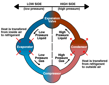
An air conditioner is a home appliance system which is designed to dehumidify and extract heat from an area. The cooling is done using a simple refrigeration cycle.

REFRIGERATION CYCLE

 In the refrigeration cycle, a heat pump transfers heat from a lower-temperature heat source into a higher-temperature heat sink. Heat would naturally flow in the opposite direction. This is the most common type of air conditioning. A refrigerator works in much the same way, as it pumps the heat out of the interior and into the room in which it stands. The most common refrigeration cycle uses an electric motor to drive a compressor.

Theroy of Refrigeratiion Cycle


WORKING PRINCIPLE OF AN AIR CONDITIONER

All air conditioning systems must have four basic elements:

Thursday, July 19, 2012

A quick Tour on LED-Animation


FLASHING LED:
The Flashing LED is not a normal LED. It has a light emitting semiconductor inside the body and it also contains a microchip flasher circuit and a current limiting resistor so the LED can be connected directly to a 5v to 9v supply. It flashes about once per second.


LED working:


When the switch is closed,the LED glows.Current Limiting Resistor is used to avoid the excess current to the LED. 

How to get correct brightness on LED? 


How LED gets damaged?

By connecting in a wrong way..


Hardwork Can Never Ever Fails..
Best Luck..

Interesting Animations to Explain Complex machines

How Sewing Machine Works?

 Second Hand Movement to control the clock:


Hardwork Can Never Ever Fails...
Best Luck...


Induction motor-animation

Wound Rotor Induction Motor:

The 3-phase stator is represented by 3 concentrated coils displaced 120o from each other. The wound rotor is also represented by 3 concentrated coils and it is rotating at the speed n=0.8 pu. With balanced 3-phase sinusoidal currents in the stator coils, a rotating magnetic field at 1.00 pu speed is established (represented by the yellow space vector) which overtakes the rotor at slip speed (1-n), thereby inducing in the rotor coils slip-frequency voltages and corresponding currents

 Hardwork Can Never Ever Fails..
 Best Luck..

DC Machine-Animation

DC Machine:

The action of the commutator is to produce a fixed spatial distribution of current directions in the armature conductors independent of shaft rotation. The field created by these currents (armature reaction) is horizontally directed and is represented by the space vector Ia. The field established by the excitation of the stator poles is directed along the vertical axis and is represented by the space vector  λf . The electromagnetic torque may be expressed as Te = k( Ia x λf  ) .

 Hardwork Can Never Ever Fails...

Best Luck...

Three phase inverter-Animation

Three Phase Inverter:

The topology of a three-phase inverter consists of  3 legs; each leg includes a switch in either the up or down position. The resulting eight possible switching configurations give rise to 6 active voltage space vectors and 2 zero vectors. The animation shows a specific sequencing of the 8 states where the active vectors rotate in discrete 60o steps.

 Hardwork Can Never Ever Fails...
 Best Luck...

Wednesday, July 18, 2012

Ethernet Bus-Animation

 Ethernet Bus:


This is a coax based Ethernet network where all machines are daisy chained using RG58 coaxial cable (sometime referred to as Thin Ethernet or Thin-net).
Machine 2 wants to send a message to machine 4, but first it 'listens' to make sure no one else is using the network.

Collision :

This animation starts with machine 2 and machine 5 both trying to transmit simultaneously.
The resulting collision destroys both signals and each machine knows this has happened because they do not 'hear' their own transmission within a given period of time (this time period is the propagation delay and is equivalent to the time it takes for a signal to travel to the furthest part of the network and back again).

Using Hub:


An Ethernet hub changes the topology from a 'bus' to a 'star wired bus', here's how it works.
Again, machine 1 is transmitting data to machine 4, but this time the signal travels in and out of the hub to each of the other machines.
As you can see, it is still possible for collisions to occur but hubs have the advantage of centralised wiring, and they can automatically bypass any ports that are disconnected or have a cabling fault. This makes the network much more fault tolerant than a coax based system where disconnecting a single connection will bring the whole network down.

Using Switch: 

 To overcome the problem of collisions and other effects on network speed, a switch is used.

With a switch, machines can transmit simultaneously, in this case 1 & 5 first, and then 2 & 4. As you can see, the switch reads the destination addresses and 'switches' the signals directly to the recipients without broadcasting to all of the machines on the network.
This 'point to point' switching alleviates the problems associated with collisions and considerably improves network speed. 


Hardwork can Never Ever Fails...
Best luck...


Token Ring and Token Bus-Working Animation

Token Ring

At the start, a free Token is circulating on the ring, this is a data frame which to all intents and purposes is an empty vessel for transporting data. To use the network, a machine first has to capture the free Token and replace the data with its own message.

In the example above, machine 1 wants to send some data to machine 4, so it first has to capture the free Token. It then writes its data and the recipient's address onto the Token (represented by the yellow flashing screen).
The packet of data is then sent to machine 2 who reads the address, realizes it is not its own, so passes it on to machine 3. Machine 3 does the same and passes the Token on to machine 4.
This time it is the correct address and so number 4 reads the message (represented by the yellow flashing screen). It cannot, however, release a free Token on to the ring, it must first send the message back to number 1 with an acknowledgement to say that it has received the data (represented by the purple flashing screen).
The receipt is then sent to machine 5 who checks the address, realizes that it is not its own and so forwards it on to the next machine in the ring, number 6.
Machine 6 does the same and forwards the data to number 1, who sent the original message.
 

 Token Bus


A Token Ring hub simply changes the topology from a physical ring to a star wired ring. The Token still circulates around the network and is still controlled in the same manner, however, using a hub or a switch greatly improves reliability because the hub can automatically bypass any ports that are disconnected or have a cabling fault.


Hardwork Can never Ever Fails...
Best Luck....

Electronics Animations

Moving Images makes the concepts more understandable.
We need teachers, who are ready to use the web for teaching the fundamentals of electronics.

Another fantastic collection of animations for electronics concepts is available here.

Please CLICK HERE view the Animations.

(Java Applet is required to view the contents)

Tuesday, July 17, 2012

Electric motor and generator-Basic working Animations

Click below to view..
electric motors animation


Hardwork Can Never Ever fails..
Best Luck...

FM modulator-Animation

FM Modulator
     frequency modulation (FM) conveys information over a carrier wave by varying its instantaneous frequency.


 Hardwork Can Never Ever  Fails...
Best Luck...

Sine Wave generation in oscilloscope-Animation


Hardwork Can Never Ever fails...
Best Luck...


AC MOTORS


AC motor


An AC motor is an electric motor driven by an alternating current.

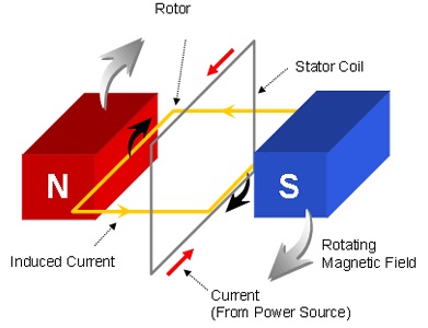
It commonly consists of two basic parts, an outside stationary stator having coils supplied with alternating current to produce a rotating magnetic field, and an inside rotor attached to the output shaft that is given a torque by the rotating field.

There are two main types of AC motors, depending on the type of rotor used. The first type is the induction motor, which runs slightly slower than the supply frequency. The magnetic field on the rotor of this motor is created by an induced current. The second type is the synchronous motor, which does not rely on induction and as a result, can rotate exactly at the supply frequency or a sub-multiple of the supply frequency.


A current is passed through the coil, generating a torque on the coil. Since the current is alternating, the motor will run smoothly only at the frequency of the sine wave. It is called a synchronous motor.


One of the drawbacks of this kind of AC motor is the high current which must flow through the rotating contacts. In common AC motors the magnetic field is produced by an electromagnet powered by the same AC voltage as the motor coil. The coils which produce the magnetic field are sometimes referred to as the "stator", while the coils and the solid core which rotates is called the "armature". 


OPERATING PRINCIPLES 

  • AC Motors Convert Electric Energy into Mechanical Energy
    • When a conductor is moving across a magnetic field a voltage is induced
    • If the conductor is part of a closed circuit there will be a current induced
    • In a motor, the induction principle is utilized in reverse
    • A live conductor is placed in a magnetic field
    • The conductor is influenced by a force which tries to move it through the magnetic field
  • The AC motor is made up of two parts
    • Stator  -The stationary section that contain the windings (magnetic field)
    • Rotor – The rotating section that contains the conductors.
Fig 6.2 The AC Motor principles operation


Sunday, July 15, 2012

Johnson counter-Working Animation

Johnson Counter:

A Johnson counter (or switchtail ring counter, twisted-ring counter, walking-ring counter, or Moebius counter) is a modified ring counter, where the output from the last stage is inverted and fed back as input to the first stage. The register cycles through a sequence of bit-patterns, whose length is equal to twice the length of the shift register, continuing indefinitely. These counters find specialist applications, including those similar to the decade counter, digital-to-analog conversion, etc. They can be implemented easily using D- or JK-type flip-flops.

Working:

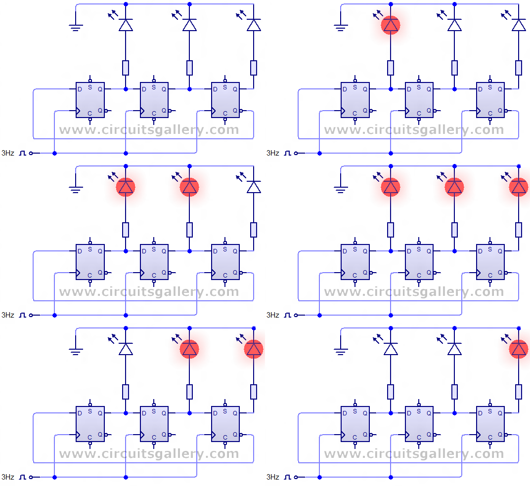
        circuit diagram represents a 3 bit Johnson counter using 7474 D flip flop. You can easily extent this     circuit up to 4 bit, 5 bit, etc. by adding flip flops after 3rd flips flop.

  • A single 7474 IC consist of 2 flip flops so you need two 7474 ICs for implementing Johnson counter.
  • Initially all the flip flops are cleared, so the time inverted output (Q’) of 3rd flip flop is high or logic 1.
  • This logic 1 is appears at the input of 1st flip flop. During the first clock pulse this logic 1 is transferred to the output of 1st flip flop. Thus the total output of Johnson counter is 100.
  • Then input of 1st and 2nd flip flop is logic 1 and after the second clock pulse these inputs appear at the outputs of 1st and 2nd flip flop. So the total output is 110.
  • Similarly for the next clock pulse, the output will be 111.
  • During this state (111) the time inverted output (Q’) is logic 0. This 0 is fed to the 1st flip flop. Then the 0 will circulate through the flip flops as 011,001,000.                                                         

Transistor acts as a switch

The above shown the working of transistor as a switch..


Hardwork can never ever fails..
Best Luck...

N-channel JFET -Working Animation

Click below to view the animation
Working Animation


Hardwork Can Never Ever Fails...
Best Luck..

N channel Enhancement MOSFET-Working Animation

Click Below
Working Animation


Hardwork Can Never Ever Fails...
Best Luck...

Wednesday, July 11, 2012

555 TIMER


A 555 timer is a type of integrated circuit, also known as a chip, which is extremely popular for a variety of purposes. Its main use is as a timer, but it can also be used as a multivibrator.

The 555 timer takes its name from the fact that the original model had three resistors each rated at five thousand ohms. The first model was formally known as the SE555/NE555 and marketed as the IC Time Machine. At the time of its 1971 release, the 555 timer was the only commercially available timer circuit. Today there are many different models from different companies, though nearly all manufacturers include 555 as part of the model number because it’s such a recognizable name.
There are two different types of 555 timer, both being eight-pin chips. The most common one is the rectangular ‘V’ package, which has four pins down each side. The other version, which used to be the most common but has now fallen from favor somewhat, is the circular ‘T’ package.
The eight pins carry out the following functions:
  1. Ground, which acts as a safety measure as with electrical plugs
  2. Trigger, which passes on voltage to start the timing operations
  3. Output, which carries voltage to the device using the timer
  4. Reset, which is used to end the timing operation
  5. Control voltage, an optional pin used for controlling the timer from outside the main circuit set-up
  6. Threshold, which determines how long the timer should output voltage in each on/off cycle – in other words, how long the timing interval should be
  7. Discharge, connected to a capacitor which also influences the timing interval
  8. V+, which is the voltage input
There are three different types of use for a 555 timer. Monostable operation is when the output signal simply switches between the default off position and a temporary on position at regular intervals, which is most commonly used for timers. Astable operation is when the output voltage rises and falls in a set pattern, making it an oscillator. As the pattern can be varied, it can be used for any purpose which requires a particular tone pattern. Bistable operation is when the signal can be held in one of two positions, meaning the 555 timer can act as the smallest possible unit of computer memory.


Tuesday, July 10, 2012

4 bit ripple counter working Animation

Ripple Counter

               An asynchronous (ripple) counter is a single JK-type flip-flop, with its J (data) input fed from its own inverted output. This circuit can store one bit, and hence can count from zero to one before it overflows (starts over from 0). This counter will increment once for every clock cycle and takes two clock cycles to overflow, so every cycle it will alternate between a transition from 0 to 1 and a transition from 1 to 0. Notice that this creates a new clock with a 50% duty cycle at exactly half the frequency of the input clock.

Click below to see the animation

 Ripple Counter

Hardwork Can  never Ever Fails...

Best Luck...

Monday, July 09, 2012

Binary Decoder working Animation

Click Below:

Binary Decoder animation

Hardwork Can Never Ever  Fails..
Best Luck..

Brige Rectifier Working animation

Click Below:
Bridge Rectifier

Hardwork Can Never Ever Fails...
Best Luck..

High Pass Filter -working and Animation

Click Below to see the animation of high pass filter
High pass filter animation


Hardwork Can Never Ever Fails...
Best Luck...

Time Division Multiplexing-Animation

TDM:

     Time division multiple access (TDMA) is a channel access method for shared medium networks. It allows several users to share the same frequency channel by dividing the signal into different time slots.

Click Below to see the animation:


Hardwork Can Never Ever Fails..
Best Luck...

Quadrature amplitude modulation-Animation

QAM:

       Quadrature amplitude modulation (QAM)  is both an analog and a digital modulation scheme. It conveys two analog message signals, or two digital bit streams, by changing (modulating) the amplitudes of two carrier waves, using the amplitude-shift keying (ASK) digital modulation scheme or amplitude modulation (AM) analog modulation scheme. The two carrier waves, usually sinusoids, are out of phase with each other by 90° and are thus called quadrature carriers or quadrature components — hence the name of the scheme. The modulated waves are summed, and the resulting waveform is a combination of both phase-shift keying (PSK) and amplitude-shift keying (ASK), or (in the analog case) of phase modulation (PM) and amplitude modulation.

Click below to view the animation :

Hardwork Can Never Ever Fails..
Best Luck...

Pulse code modulation-Animation

PCM

              Pulse-code modulation (PCM) is a method used to digitally represent sampled analog signals. It is the standard form for digital audio in computers and various Blu-ray, DVD and Compact Disc formats, as well as other uses such as digital telephone systems. A PCM stream is a digital representation of an analog signal, in which the magnitude of the analog signal is sampled regularly at uniform intervals, with each sample being quantized to the nearest value within a range of digital steps.


click below to see the animation :

pcm animation

Hardwork Can Never Ever fails...
Best Luck...