As the 2 stroke engine animation below shows, a two-stroke engine in its purest form is extremely simple in construction and operation, as it only has three primary moving parts such as the piston, connecting rod, and crankshaft.
The subject of the 2 stroke engine animation is known as a case-reed type because induction is controlled by a reed valve mounted in the side of the crankcase.

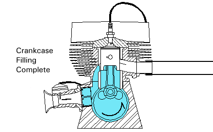
As the piston moves upward, a vacuum is created beneath the piston in the enclosed volume of the Tcrankcase. Air flows through the reed valve and carburetor to fill the vacuum created in the crankcase. The intake phase is completed when the piston reaches the top of the stroke.
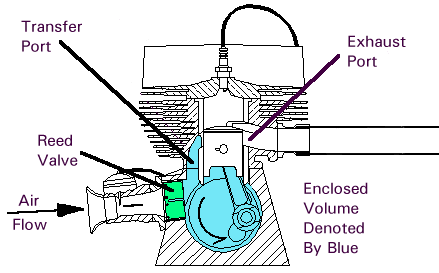
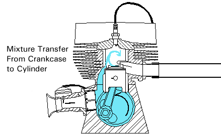
During the down stroke, the falling piston creates a positive pressure in the crankcase which causes the reed valve to close. The mixture in the crankcase is compressed until the piston uncovers the transfer port openings, at which point the mixture flows up into the cylinder. The engine depicted in the 2 stroke engine animation and diagrams is known as a loop-scavenged two-stroke because the incoming mixture describes a circular path.
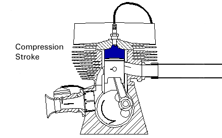
Mixture transfer continues until the piston once again rises high enough to shut off the transfer ports . Let's fast-forward about 25 degrees of crank rotation to the point where the exhaust port is covered by the piston. The trapped mixture is now compressed by the upward moving piston at the same time that a new charge is being drawn into the crankcase down below.
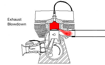
If you watch the 2 stroke engine animation you will see this event is timed such that the burning mixture reaches peak pressure slightly after top dead center. The expanding mixture drives the piston downward until it begins to uncover the exhaust port. The majority of the pressure in the cylinder is released within a few degrees of crank rotation after the port begins to open:
Residual exhaust gases are pushed out the exhaust port by the new mixture entering the cylinder from the transfer ports. In the 2 stroke engine animation you can see the gases moving out of the exhaust at the same time new mixture is entering the cylinder. That completes the chain of events for the basic two-stroke cycle.
The 2 stroke engine animation demonstration has an added device commonly known as an expansion chamber attached to the exhaust port. The expansion chamber (an improperly named device) utilizes sonic energy contained in the initial sharp pulse of exhaust gas exiting the cylinder to supercharge the cylinder with fresh mixture. This device is also known as a tuned exhaust.

The sonic compression wave resulting from this abrupt release of cylinder pressure travels down the exhaust pipe until it reaches the beginning of the divergent cone, or diffuser, of the expansion chamber. From the perspective of the sound waves reaching this junction, the diffuser appears almost like an open-ended tube in that part of the energy of the pulse is reflected back up the pipe, except with an inverted sign; a rarefaction, or vacuum pulse is returned.
Watch the 2 stroke engine animation closely to see the waves reflected back up the pipe. The angle of the walls of the cone determine the magnitude of the returned negative pressure, and the length of the cone defines the duration of the returning waves

The negative pressure assists the mixture coming up through the transfer ports, and actually draws some of the mixture out into the exhaust header. The original pressure pulse is still making its way down the expansion chamber, although a considerable portion of its energy was given up in creating the negative pressure waves.

This pulse is timed to reach the exhaust port after the transfer ports close, but before the exhaust port closes. The returning compression wave pushes the mixture drawn into the header by the negative pressure wave back into the cylinder, thus supercharging a bigger charge than normal the engine. The straight section of pipe between the two cones exists to ensure that the positive waves reaches the exhaust port at the correct time.

Since this device uses sonic energy to achieve supercharging, it is regulated by the speed of sound in the hot exhaust gas, the dimensions of the different sections of the exhaust system, and the port durations of the engine. Because of this, it is only effective for a very narrow RPM range.
No comments:
Post a Comment
Thank you for your valuable suggestion. If you feel this post useful, please share our Blog with others!!! Comments just for Backlinking your Website or Blog will be Deleted...