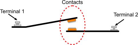
Each relay has two mechanical parts inside. The first one is the contact(s) of the relay. The contacts operates similarly to the contacts of a simple switch or pushbutton. You should consider the contacts as a pair of metals like the following diagram:
As for the NC contacts, it works exactly opposite as the NO contacts. Look the following animation:
A combination of contacts
A relay may have a combination of the above contacts. Look at the following illustration
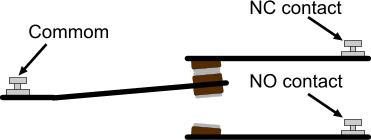
In this case, there is a 3rd terminal called "COMMON". The NO and NC contacts are referred to the COMMON terminal. Between the NC and the NO contact, there is no contact at any time! The following animation shows how this pair operates:
The last part - WHO move the common contact of the relay?
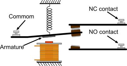
This is the last part of the relay operation. The device that forces the terminal to move, is actually an electromagnet! A coil is placed right under the contact. When current is flown through this coil, a magnetism is created. This magnetism can overcome the force of the spring and can pull the contact towards it, thus it changes it's position! And due to the fact that the contact is usually a small piece of metal not capable to be pulled by the electromagnet, another piece of metal is attached to the common. This piece of metal is so called "Armature". Following is (at last) the complete illustration of the basic relay:
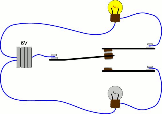
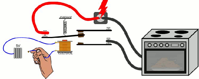
Now, imagine that someone wants to control a 220Volts 1 K-Watt load with a command that comes from a 5 Volts battery. A load-Relay should be used for this application. The Coil of the relay is driven with the 5 Volts. The contacts from this relay (NO) will be connected in series with the power supply of the load. Thus, the load will only operate when the relay is actuated. Our friend bellow will turn on an electric oven bare-handed!!!
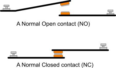
The two terminals operates as a switch. When the contacts are 'in contact' then the current flows from Terminal 1 to Terminal 2. There are two types of contacts: the NO and the NC. NO stands for Normal Open contact, while NC stands for Normal Closed contact. The Normal Open is a contact like the one showed in the previous illustration. When the contact is still, then no current flows through it (because it is an OPEN circuit). On the other hand, a Normal Closed contact allows the current to flow when the contact is still. Bellow i illustrate both of these contacts:
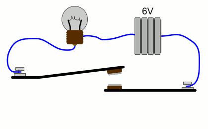
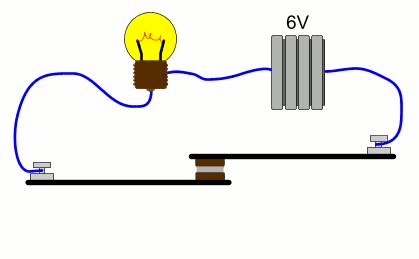
You may notice that the NC contact is turned upside-down compared to the NO contact. This is done in purpose. This way, both contacts (NO and NC) will change state if a force is applied to the left metal heading from UP to DOWN. The following animation shows how a NO contact operates by lighting a light bulb:
As for the NC contacts, it works exactly opposite as the NO contacts. Look the following animation:
A combination of contacts
In this case, there is a 3rd terminal called "COMMON". The NO and NC contacts are referred to the COMMON terminal. Between the NC and the NO contact, there is no contact at any time! The following animation shows how this pair operates:
And WHO defines the NORMAL state?
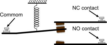
OK, we have the NORMAL open and NORMAL closed contact. But which state is considered as NORMAL? Going one step closer to the relay operation, we find the spring. This spring defines the NORMAL position of the COMMON contact. If you see the above 3 animations, you will notice that one time an F force is applied to the COMMON terminal, and the other time there is no force applied. Well, this is actually wrong. There is indeed another force that pulls the contact towards UP and this force is applied ALL the time. This force comes from the spring. Look the following image:
Now you can see who is pulling the COMMON terminal UP all the time. So the spring defines what is the NORMAL state, and thus defines which contact is the NORMAL OPEN and which the NORMAL CLOSED. In other words, the NORMAL state is defined as the state that there is NO other force applied to the COMMON terminal except the one from the spring.
The last part - WHO move the common contact of the relay?
This is the last part of the relay operation. The device that forces the terminal to move, is actually an electromagnet! A coil is placed right under the contact. When current is flown through this coil, a magnetism is created. This magnetism can overcome the force of the spring and can pull the contact towards it, thus it changes it's position! And due to the fact that the contact is usually a small piece of metal not capable to be pulled by the electromagnet, another piece of metal is attached to the common. This piece of metal is so called "Armature". Following is (at last) the complete illustration of the basic relay:
Now, imagine that someone wants to control a 220Volts 1 K-Watt load with a command that comes from a 5 Volts battery. A load-Relay should be used for this application. The Coil of the relay is driven with the 5 Volts. The contacts from this relay (NO) will be connected in series with the power supply of the load. Thus, the load will only operate when the relay is actuated. Our friend bellow will turn on an electric oven bare-handed!!!
No comments:
Post a Comment
Thank you for your valuable suggestion. If you feel this post useful, please share our Blog with others!!! Comments just for Backlinking your Website or Blog will be Deleted...