Showing posts with label Hobby Circuits. Show all posts

Wednesday, December 24, 2014

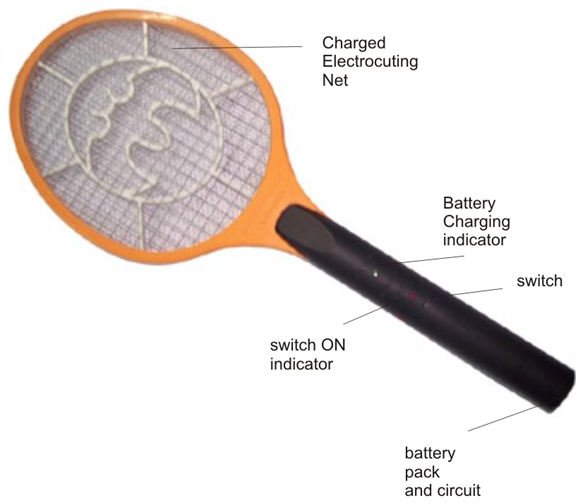
How Mosquito Racket works?


Parts: 

1. Power Supply
2. Oscillator
3. Transformer(Step-up)
4, Final mesh-nets

The circuit consists of a flyback topology transformer driven by a general NPN transistor 2SD965.

The feedback coil of transformer is of 10 turns, the primary is of 40 turns and the output or secondary coil is of 450 turns (40:450).

When this circuit is run by giving input of 3 Volts, the transformer generates about 2000-4000 volts at zero load, and the output is then coupled 3 times by using three IN4007 diodes and suitable capacitors, thus reaching our need of 5000-10,000 volts.

  The moment a mosquito or any bug comes in contact with the meshes, the stored high voltage in the capacitor discharges violently through the body of the entangled bug creating a big spark and electrocuting it instantly.

Tuesday, January 08, 2013

Electrical Jumper

Wire Jumper

A wire jumper is a small piece of uninsulated wire that is place in two adjacent PCB holes and soldered into position based on our requirement.It is called jumper because,The wire jumps the electrical signal or power from one pcb hole to another.

Standard Wire Jumper

Sometimes wires may be used to make a connection between two contacts.


Plastic Jumper

Jumpers are also made up of non-conductive form of plastic for our convenience.When this plastic jumper is placed on the pins it made a connection between two pins.


Courtesy:imagesco.com 


Hardwork Can Never Ever Fails..
Best Luck...

Friday, August 31, 2012

CAR ANTI - THEFT GUARD

Here is an easy-to-build car anti-theft guard. The circuit, shown in Fig. 1, is simple and easy to understand. When key-operated switch S2 of the car is turned on, 12V DC supply from the car battery is extended to the entire circuit through polarity-guard diode D5. Blinking LED1 flashes to indicate that the guard circuit is enabled. It works off 12V power supply along with current-limiting resistor R4 in series.


Fig. 1: Circuit of car anti-theft guard 
When the car door is closed, door switch S1 is in 'on' position and 12V power supply is available across resistor R1, which prevents transistor T1 from conducting. In this position, anti-theft guard circuit is in sleep mode.

When someone opens the car door, switch S1 becomes 'off' as shown in Fig. 2. As a result, transistor T1 conducts to fire relay-driver SCR1 (BT169) after a short delay introduced by capacitor C1. Electromagnetic relay RL1 energises and its N/O contact connects the power supply to piezobuzzer PZ1, which starts sounding to indicate that someone is trying to steal your car. To reset the circuit, turn off switch S2 using car key. This will cut-off the power supply to the circuit and stop the buzzer sound.


Fig. 2: Wiring diagram for door switch
Assemble the circuit on a general-purpose PCB and house in a small box. Connect switch S1 to the car door and keep piezobuzzer PZ1 at an appropriate place in the car.