The python implementation, mathematical background, and noise removal using Fourier Transform are explored in this VIDEO..
Showing posts with label Advanced Topics. Show all posts
Showing posts with label Advanced Topics. Show all posts
Sunday, May 16, 2021


Monday, May 10, 2021
Basics of Fourier Transform
Thursday, July 16, 2015
Friday, February 08, 2013
What are MEMS?
Think if we can integrate a GPS System on every Parcel we are sending via Courier or Post. It will be very easy for us to track the current location of the Parcel and the Handling of the Parcel. But, the system should be small like a Chip, and it should be of least cost. Don't forget that the GPS System has a Processor and an Antenna to receive the signals from the Satellite. How can we integrate the entire system inside a Small Chip? Here comes the application of MEMS.
MEMS is an emerging technology in which Microscopic Machines are developed by the tools and techniques that were developed for the Integrated Circuit (IC)ndustry.
MEMS is an emerging technology in which Microscopic Machines are developed by the tools and techniques that were developed for the Integrated Circuit (IC)ndustry.
 |
| MEMS structure |
Micro-Electro Mechanical systems (MEMS) is a technology that combines
computers with tiny mechanical devices such as sensors, valves, gears,
mirrors, and actuators embedded in semiconductor chips.
These machines are built on standard silicon wafers.
MEMS are made up of components between 1 to 100 micrometres in size
(i.e. 0.001 to 0.1 mm), and MEMS devices generally range in size from 20
micrometres (20 millionths of a metre) to a millimetre (i.e. 0.02 to
1.0 mm).
They usually consist of a Central Unit that processes data (the
microprocessor) and several components that interact with the outside
such as Microsensors.
 |
| Components of MEMS |
What are the Advantages of MEMS?
By utilizing this
technology, it is possible to integrate both Microelectronic circuits
and Mechanical structures on the same chip, enabling monolithic
integration while reducing the microsystem size and cost considerably.
What are the Applications of MEMS?
 |
| SMART BIOMEM (LAB ON A CHIP) |
This technology has an enormous number of application areas, including
- Automotive Eg. Accelerometers for airbag systems, Roll-over detection systems, etc.
- Biomedical Eg.Neural prosthesis devices like hearing and visual aids, Smart drug delivery systems, On Chip body fluid analysis systems, Microsurgery tools, Pacemakers
- Telecommunication Eg. Micromirrors for fiber optic switching for fast internet,Smart Antennas
- Household appliances pressure sensors for water level detection, frost sensors for refrigerators
- Consumer Applications DLP projectors, i-phone,
- Defense applications Eg. Low cost night vision, Smart munitions
Image Courtesy
www.engineersgarage.com
www.medgadget.com
Monday, November 12, 2012
How inkjet printer Works?

1. paper tray
2.printhead/cartridge assembly
3.printhead stepper motor
4. sliding rod
5.belt
6. printhead
7.ink cartridge
8.nozzles
9.ink chambers
10.droplets
11.Resistor
WORKING :
A typical inkjet receives control info from your printer driver/PC,
or may process the printout in its onboard electronics. Either way,
rollers advance a page from your paper tray (1) under a sliding printhead/cartridge assembly (2). Then, the printhead stepper motor (3) kicks in, drawing the assembly on a sliding rod (4) to its starting position, usually via a belt (5).
The printhead (6)
proper is an incredible piece of miniaturization, in some cases
fabricated via an etching process similar to semiconductor manufacture.
On some printers, the head and ink cartridge (7) are one unit. The head's microscopic nozzles (8)—anywhere from dozens to literally thousands—are outlets for incredibly tiny ink chambers (9), which are fed by the cartridge's reservoirs. Microscopic droplets (10), measured in millionths of a millionth of a liter (no, that's not a typo), fire through the nozzles.
Most inkjets (Epsons excepted) use "thermal" technology in which a tiny resistor(11)
in an ink chamber is pulsed, as needed, with intense current,
superheating the ink and vaporizing part of the droplet.
The result:
Terrific pressure blasts it out the nozzle and onto your page. (Epson employs a piezoelectric process in which applying current to a crystal in an ink chamber causes it to oscillate, ejecting the ink.) Capillary action then draws new ink into the chamber. Your text and images are built up, line by line, as the printhead assembly tracks across the page.A given chamber can repeat the heating/firing/cooling cycle thousands of times per second.
Terrific pressure blasts it out the nozzle and onto your page. (Epson employs a piezoelectric process in which applying current to a crystal in an ink chamber causes it to oscillate, ejecting the ink.) Capillary action then draws new ink into the chamber. Your text and images are built up, line by line, as the printhead assembly tracks across the page.A given chamber can repeat the heating/firing/cooling cycle thousands of times per second.
Courtesy:http://computershopper.com
Hardwork Can Never Ever Fails...
Best Luck...
How laser printer works?
Toner and the Drum
When a laser printer starts a print job, the first thing it does is apply a positive electrical charge to the drum unit. Afterwards, the laser system ‘writes’ the page image onto the drum with a negative charge, creating an electric “virtual negative” of the image.
The Toner The drum unit rotates, and as the image is written on it, it picks up toner, the laser printer equivalent of ink. The toner is positively charged, and so it sticks to the image that the laser drew. The paper presses against the drum, and receives the toner image.
The Fuser
When the paper first picks up the toner, the image is not set. Toner is a dry, dusty material, and it the electric charge cannot hold it strongly to the paper. In order to make the image permanent, the paper runs through the fuser, which heats it, and melts the toner onto the page. The paper exits the printer, and you have your print out.
How does a laser printer work with the toner?
The image below shows you how a laser printer works in conjuction with your toner cartridge. After you send a document to print - the paper travels through the printer, past the drum, toner and fuser unit and ends up as a printed page of text or graphics.

Courtesy:http://www.zinetic.co.uk
Hardwork Can Never Ever Fails..
Best Luck..
When a laser printer starts a print job, the first thing it does is apply a positive electrical charge to the drum unit. Afterwards, the laser system ‘writes’ the page image onto the drum with a negative charge, creating an electric “virtual negative” of the image.
The Toner The drum unit rotates, and as the image is written on it, it picks up toner, the laser printer equivalent of ink. The toner is positively charged, and so it sticks to the image that the laser drew. The paper presses against the drum, and receives the toner image.
The Fuser
When the paper first picks up the toner, the image is not set. Toner is a dry, dusty material, and it the electric charge cannot hold it strongly to the paper. In order to make the image permanent, the paper runs through the fuser, which heats it, and melts the toner onto the page. The paper exits the printer, and you have your print out.
How does a laser printer work with the toner?
The image below shows you how a laser printer works in conjuction with your toner cartridge. After you send a document to print - the paper travels through the printer, past the drum, toner and fuser unit and ends up as a printed page of text or graphics.
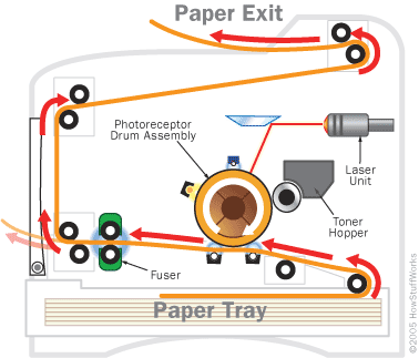
Courtesy:http://www.zinetic.co.uk
Hardwork Can Never Ever Fails..
Best Luck..
Monday, October 22, 2012
What is Quantum tunneling?

Let's say you are throwing a rubber ball against a wall. You know you don't have enough energy to throw it through the wall, so you always expect it to bounce back. Quantum mechanics, however, says that there is a small probability that the ball could go right through the wall (without damaging the wall) and continue its flight on the other side! With something as large as a rubber ball, though, that probability is so small that you could throw the ball for billions of years and never see it go through the wall. But with something as tiny as an electron, tunneling is an everyday occurrence.
Quantum tunneling is possible because of the wave-nature of matter. Confounding as it sounds, in the quantum world, particles often act likes waves of water rather than billiard balls. This means that an electron doesn't exist in a single place at a single time and with a single energy, but rather as a wave of probabilities.
What is Quantum Mechanics?
In the early 20th century some experiments produced results which could not be explained by classical physics (the science developed by Galileo Galilei, Isaac Newton, etc.).
For instance, it was well known that electrons orbited the nucleus of an atom. However, if they did so in a manner which resembled the planets orbiting the sun, classical physics predicted that the electrons would spiral in and crash into the nucleus within a fraction of a second.
Obviously that doesn't happen, or life as we know it would not exist. (Chemistry depends upon the interaction of the electrons in atoms, and life depends upon chemistry).
That incorrect prediction, along with some other experiments that classical physics could not explain, showed scientists that something new was needed to explain science at the atomic level.
Thus, quantum mechanics is the study of matter and radiation at an atomic level.
For everyday things, which are much larger than atoms and much slower than the speed of light, classical physics does an excellent job. Plus, it is much easier to use than either quantum mechanics or relativity (each of which require an extensive amount of math).
Every quantum particle is characterized by a wave function. In 1925 Erwin Schrödinger developed the differential equation which describes the evolution of those wave functions. By using Schrödinger's equation scientists can find the wave function which solves a particular problem in quantum mechanics.
The following are among the most important things which quantum mechanics can describe while classical physics cannot:
'It is impossible, absolutely impossible to explain it in any classical way'.
Richard Feynman
"[T]he atoms or elementary particles themselves are not real; they form a world of potentialities or possibilities rather than one of things or facts."
Werner Heisenberg
For instance, it was well known that electrons orbited the nucleus of an atom. However, if they did so in a manner which resembled the planets orbiting the sun, classical physics predicted that the electrons would spiral in and crash into the nucleus within a fraction of a second.
Obviously that doesn't happen, or life as we know it would not exist. (Chemistry depends upon the interaction of the electrons in atoms, and life depends upon chemistry).
 |
| Probability Density of electron in an Hydrogen Atom |
That incorrect prediction, along with some other experiments that classical physics could not explain, showed scientists that something new was needed to explain science at the atomic level.
Thus, quantum mechanics is the study of matter and radiation at an atomic level.
For everyday things, which are much larger than atoms and much slower than the speed of light, classical physics does an excellent job. Plus, it is much easier to use than either quantum mechanics or relativity (each of which require an extensive amount of math).
 |
| The d and s subs shells in the Quantum mechanics atom model |
Every quantum particle is characterized by a wave function. In 1925 Erwin Schrödinger developed the differential equation which describes the evolution of those wave functions. By using Schrödinger's equation scientists can find the wave function which solves a particular problem in quantum mechanics.
The following are among the most important things which quantum mechanics can describe while classical physics cannot:
- Discreteness of energy
- The wave-particle duality of light and matter
- Quantum tunneling
- The Heisenberg uncertainty principle
- Spin of a particle
'It is impossible, absolutely impossible to explain it in any classical way'.
Richard Feynman
[I can't accept quantum mechanics because] "I like to think the moon is there even if I am not looking at it. God does not play dice with the universe."
Albert Einstein"[T]he atoms or elementary particles themselves are not real; they form a world of potentialities or possibilities rather than one of things or facts."
Werner Heisenberg
"Anyone not shocked by quantum mechanics has not yet understood it."
Neils Bohr
"Nobody understands quantum mechanics."
Richard FeynmanSaturday, September 22, 2012
LCD AND DLP TECHNOLOGY
How LCD Projectors Work
LCD projectors employ a three-panel LCD (Liquid
Crystal Display) system, referred to as 3LCD. LCD projectors crisply
reproduce bright, naturally colored images that are easy on the eyes.
LCD projectors are also capable of detailed shadow reproduction that is
ideal for demanding business and home theater applications.

The white light from the projector lamp is split into red, green, and
blue components using two dichroic mirrors, special mirrors that only
transmit light of a specified wavelength. Each red, green and blue beam
then passes through a dedicated LCD panel made up of thousands of
miniscule pixels. An electrical current turns the panel's pixels on or
off to create the grayscale equivalent of that color channel. The three
colors are then recombined in a prism and projected through the
projector lens and onto the screen.
By using a combination of three LCDs to produce a final image,
LCD projectors are capable of billions of colors and smooth grayscale
gradations. The resolution of the image is determined by the number of
pixels in the LCD panels used. Currently LCD panels offer resolutions as
high as true HD (1920 x 1080) for home theater applications. New panels
promise resolutions as high as 4K (3840 x 2160).
How does DLP technology work?
Digital Light Processing is a
proprietary system developed by Texas Instruments, and works
differently to LCD projection. Most DLP projectors have a single chip
instead of glass panels through which light is passed, and this chip
has a reflective surface composed of thousands of tiny mirrors which
correspond to individual pixels. These mirrors can move back and forth
when light is beamed onto the chip to direct the light from individual
pixels either towards the projector lens or away from it. In order to
define colours, DLP projectors have a colour wheel that consists of
red, green and blue filters. This wheel spins between the light source
and the DLP chip and alternates the colour of the light hitting the chip
between red, green and blue. The mirrors tilt away from or into the
lens path depending on how much of each color is required for each
pixel at any given moment.

The various advantages and disadvantages of LCD and DLP projectors
mean that each is suited to different applications. Lighter, less bulky
DLP projectors are favored by presenters on the road. DLP projectors
are also very popular with home theatre enthusiasts due to the higher
colour saturation, better contrast and image stability. Entry level DLP
home theater projectors are also very affordable.
LCD projectors
are often more affordable, making them attractive for education
organizations. Their higher light output make them well suited for
classrooms and larger conference facilities, as does their increased
image sharpness which makes them good for displaying data-rich
presentations such as spreadsheets and graphs.
In terms of
market share, LCD projection technology is currently leading DLP
technology due to the larger number of projectors using the LCD system.
Sony and Epson are the largest LCD manufacturers, along with Hitachi
and Sanyo. Optoma, InFocus and BenQ, on the other hand, use DLP
technology.
Wednesday, September 05, 2012
Network-on-Chip
To meet the growing computation-intensive
applications and the needs of low-power, high-performance systems, the number
of computing resources in single-chip has enormously increased, because current VLSI technology can support such an extensive integration of
transistors. By adding many computing resources such as CPU, DSP, specific IPs,
etc to build a system in System-on-Chip, its interconnection between each other
becomes another challenging issue.
 |
| Network ON Chip |
In most System-on-Chip applications, a
shared bus interconnection which needs an arbitration logic to serialize
several bus access requests, is adopted to communicate with each integrated
processing unit because of its low-cost and simple control characteristics.
However, such shared bus interconnection has some limitation in its scalability
because only one master at a time can utilize the bus which means all the bus
accesses should be serialized by the
arbitrator. Therefore, in such an environment where the number of bus
requesters is large and their required bandwidth for interconnection is more
than the current bus, some other interconnection methods should be considered.
Such scalable bandwidth requirement can be satisfied
by using on-chip packet-switched micro-network of interconnects, generally
known as Network-on-Chip (NoC) architecture. The basic idea came from
traditional large-scale multi-processors and distributed computing networks.
The scalable and modular nature of NoCs and their support for efficient on-chip
communication lead to NoC-based system implementations. Even though the current
network technologies are well developed and their supporting features are
excellent, their complicated configurations and implementation complexity make
it hard to be adopted as an on-chip interconnection methodology. In order to
meet typical SoCs or multi-core processing environment, basic module of network
interconnection like switching logic, routing algorithm and its packet
definition should be light-weighted to result in easily implemental solutions.
Thursday, August 30, 2012
What's a Smith chart?

What is a Smith chart? It's really
just a plot of complex reflection overlaid with an impedance
and/or admittance grid referenced to a 1-ohm characteristic
impedance. That's it! Transmission coefficient, which equals unity
plus reflection coefficient, may also be plotted (see below). You
can find books and articles describing how a Smith chart is a graphical
representation of the transmission line equations and the mathematical
reasons for the circles and arcs, but these things don't really
matter when you need to get the job done. What matters is knowing
the basics and how to use them, like always.
The Smith chart contains almost
all possible impedances, real or imaginary, within one circle. All
imaginary impedances from - infinity to + infinity are represented,
but only positive real impedances appear on the "classic"
Smith chart. Yes, it is possible to go outside the Smith chart "unity"
circle, but only with an active device because this implies negative
resistance.
One thing you give up when plotting
reflection coefficients on a Smith chart is a direct reading of
a frequency axis. Typically, plots that are done over any frequency
band have markers calling out specific frequencies.
Why use a Smith chart?
It's got all those funny circles and arcs, and good ol' rectangular
plots are much better for displaying things like VSWR, transmission
loss, and phase, right? Perhaps sometimes a rectangular plot is
better, but a Smith chart is the RF engineer's best friend! It's
easy to master, and it adds an air of "analog coolness"
to presentations, which will impress your friends, if not your dates!
A master in the art of Smith-charting can look at a thoroughly messed
up VSWR of a component or network, and synthesize two or three simple
networks that will impedance-match the circuit in his head!
Impedance and admittance
A quick refresher on the basic
quantities that have units of ohms or its reciprocal, Siemens (sometimes
called by its former name, mhos), is helpful since many of them
will be referenced below. We all think of resistance (R) as the
most fundamental of these quantities, a measure of the opposition
to current flow that causes a potential drop, or voltage, according
to Ohms Law: V=I*R. By extension, impedance (Z) is the steady state
AC term for the combined effect of both resistance and reactance
(X), where Z=R+jX. (X=jwL for an inductor, and X=1/jwC for a capacitor,
where w is the radian frequency or 2*pi*f.) Generally, Z is a complex
quantity having a real part (resistance) and an imaginary part (reactance).
We often think in terms of impedance
and its constituent quantities of resistance and reactance. These
three terms represent "opposition" quantities and are
a natural fit for series-connected circuits where impedances add
together. However, many circuits have elements connected in parallel
or "shunt" that are a natural fit for the "acceptance"
quantity of admittance (Y) and its constituent quantities of conductance
(G) and susceptance (B), where Y=G+jB. (B=jwC for a capacitor, and
B=1/jwL for an inductor.) Admittances add together for shunt-connected
circuits. Remember that Y=1/Z=1/(R+jX), so that G=1/R only if X=0,
and B=-1/X only if R=0.
When working with a series-connected
circuit or inserting elements in series with an existing circuit
or transmission line, the resistance and reactance components are
easily manipulated on the "impedance" Smith chart.
Similarly, when working with a parallel-connected circuit or inserting
elements in parallel with an existing circuit or transmission line,
the conductance and susceptance components are easily manipulated
on the "admittance" Smith chart. The "immittance"
Smith chart simply has both the impedance and admittance
grids on the same chart, which is useful for cascading series-connected
with parallel-connected circuits.
Subscribe to:
Posts (Atom)