Wednesday, November 21, 2012

Sound Waves

SOUND:

Sound is a mechanical wave that is an oscillation of pressure transmitted through a solid, liquid, or gas, composed of frequencies within the range of hearing.Sound also travels through plasma.

Sound is a sequence of waves of pressure that propagates through compressible media such as air or water. Sound that is perceptible by humans has frequencies from about 20 Hz to 20,000 Hz.


The behavior of sound propagation is generally affected by three things:
  • A relationship between density and pressure. This relationship, affected by temperature, determines the speed of sound within the medium.
  • The propagation is also affected by the motion of the medium itself. For example, sound moving through wind. Independent of the motion of sound through the medium, if the medium is moving, the sound is further transported.
  • The viscosity of the medium also affects the motion of sound waves. It determines the rate at which sound is attenuated. For many media, such as air or water, attenuation due to viscosity is negligible.


simple simulation of sound waves traveling in air

Longitudinal Waves and Tuning Forks

Sound waves are produced by vibrating objects. Whether it be the sound of a person's voice, the sound of a piano, the sound of a trombone or the sound of a physics book slamming to the floor, the source of the sound is always a vibrating object.

A tuning fork serves as a useful illustration of how a vibrating object can produce sound. The fork consists of a handle and two tines. When the tuning fork is hit with a rubber hammer, the tines begin to vibrate. The back and forth vibration of the tines produce disturbances of surrounding air molecules. As a tine stretches outward from its usual position, it compresses surrounding air molecules into a small region of space, this creates a high pressure region next to the tine.

As the tine then moves inward from its usual position, air surrounding the tine expands; this produces a low pressure region next to the tine. The high pressure regions are known as compressions and the low pressure regions are known as rarefactions. As the tines continue to vibrate, an alternating pattern of high and low pressure regions are created. These regions are transported through the surrounding air, carrying the sound signal from one location to another.


Sound waves of Tuning Fork

Here is the link shows the animation on the sound waves.....

Animations of Sound Waves


Tuesday, November 20, 2012

Energy levels and radiations-Animation


Electrons in a hydrogen atom must be in one of the allowed energy levels. If an electron is in the first energy level, it must have exactly -13.6 eV of energy. If it is in the second energy level, it must have -3.4 eV of energy. An electron in a hydrogen atom cannot have -9 eV, -8 eV or any other value in between.

Let's say the electron wants to jump from the first energy level, n = 1, to the second energy level n = 2. The second energy level has higher energy than the first, so to move from n = 1 to n = 2, the electron needs to gain energy. It needs to gain (-3.4) - (-13.6) = 10.2 eV of energy to make it up to the second energy level.

The electron can gain the energy it needs by absorbing light. If the electron jumps from the second energy level down to the first energy level, it must give off some energy by emitting light. The atom absorbs or emits light in discrete packets called photons, and each photon has a definite energy. Only a photon with an energy of exactly 10.2 eV can be absorbed or emitted when the electron jumps between the n = 1 and n = 2 energy levels.
The energy that a photon carries depends on its wavelength. Since the photons absorbed or emitted by electrons jumping between the n = 1 and n = 2 energy levels must have exactly 10.2 eV of energy, the light absorbed or emitted must have a definite wavelength. This wavelength can be found from the equation
E = hc/l,
where E is the energy of the photon (in eV), h is Planck's constant (4.14 x 10⁻¹⁵ eV s) and c is the speed of light (3 x 10⁸ m/s). Rearranging this equation to find the wavelength gives
l = hc/E.
A photon with an energy of 10.2 eV has a wavelength of 1.21 x 10⁻⁷ m, in the ultraviolet part of the spectrum. So when an electron wants to jump from n = 1 to n = 2, it must absorb a photon of ultraviolet light. When an electron drops from n = 2 to n = 1, it emits a photon of ultraviolet light.
The step from the second energy level to the third is much smaller. It takes only 1.89 eV of energy for this jump. It takes even less energy to jump from the third energy level to the fourth, and even less from the fourth to the fifth.
What would happen if the electron gained enough energy to make it all the way to 0eV? The electron would then be free of the hydrogen atom. The atom would be missing an electron, and would become a hydrogen ion.


Click below to view the animation
Energy level animation


Hardwork Can Never Ever Fails.
Best luck..

Introduction to electrons in crystals


A meaningful discussion of semi­conductors requires some background on how electrons move through solids. The free-electron gas model simply assumes that the electrons move through an empty periodic box. But of course, to describe a real solid the box should really be filled with the countless atoms around which the conduction electrons move. 

Click below to view the animation
electrons animation


Hardwork Can Never Ever Fails..
Best Luck..

ULTRA SOUND

Ultra Sound:
Ultrasound is a cyclic sound pressure wave with a frequency greater than the upper limit of the human hearing range. Ultrasound is thus not separated from audible sound based on differences in physical properties only the fact that humans cannot hear it.
Ultrasound is used in many different fields. Ultrasonic devices are used to detect objects and measure distances. Ultrasonic imaging is used in human and veterinary medicine. In non-destructive testing of products and structures, ultrasound is used to detect invisible flaws. For Industries, ultrasound is used for cleaning and for mixing, and to accelerate chemical processes. 

Ultrasonics is the application of ultrasound. Ultrasound can be used for imaging, detection, measurement, and cleaning. At higher power levels ultrasonics are useful for changing the chemical properties of substances.

File:Ultrasound range diagram.svg

Figure. Ranges of Ultra sound

A common use of ultrasound is in range finding; this use is also called SONAR, (sound navigation and ranging). An ultrasonic pulse is generated in a particular direction. If there is an object in the path of this pulse, part or all of the pulse will be reflected back to the transmitter as an echo and can be detected through the receiver path. By measuring the difference in time between the pulse being transmitted and the echo being received, it is possible to determine the distance.


Principle of Active SONAR

Here is the animation for the Ultrasound....

Animation of ultra sound

Monday, November 19, 2012

Distributed Antenna System (DAS)


The concept of a Distributed Antenna System, DAS has many advantages in some applications. A Distributed antenna system, DAS is a network of antennas spaced apart from each other, but connected to a common source. In this way the DAS is able to provide wireless or radio coverage within a given area.
The idea of a distributed antenna system is being adopted increasingly as it enables a number of advantages to be gained. However this is at the cost of a larger more complicated system. Nevertheless, distributed antenna systems are being used in a variety of areas to enable the right coverage to be gained for several applications.
Although the concept of distributed antenna systems has been known about for many years, it is with the increased deployment of wireless systems within buildings and other difficult coverage areas that the idea of distributed antenna systems has come to the fore.


Advantages of using a distributed antenna system
  • Better defined coverage
  • Fewer coverage holes
  • Same coverage using a lower overall power
  • Lowers health risk as a result of using lower overall power levels
  • Individual antennas do not need to be as high as a single antenna for the equivalent coverage
Disadvantages of using a distributed antenna system
  • Higher cost as a result of additional infrastructure required
  • Possible greater visual impact in some applications as a result of greater number of antennas, although they are likely to be much lower in height.

Basic concept of a distributed antenna system

The basic idea behind the distributed antenna system is to utilise several different antennas over the required coverage area. Using this approach the overall power required is less because these more localised antennas can be placed more effectively for a small area, rather than having a single, larger antenna that is a compromise for the wider coverage needed. By adopting a distributed antenna system approach, this helps overcome the shadowing and penetration losses because a line of sight link is available more frequently. As a result the levels of absorption are lower and this means the overall power levels can be reduced.

www.RadioElectronics.com

10-Gigabit Ethernet (10GBASE-T)


10-Gigabit Ethernet (10GBASE-T), being standardized in IEEE 802.3a, is a telecommunication technology that offers data speeds up to 10 billion bits per second. Built on the Ethernet technology used in most of today's local area networks (LANs), 10-Gigabit Ethernet is described as a "disruptive" technology that offers a more efficient and less expensive approach to moving data on backbone connections between networks while also providing a consistent technology end-to-end. Using optical fiber, 10-Gigabit Ethernet can replace existing networks that use ATM switches and SONET multiplexers on an OC-48 SONET ring with a simpler network of 10-Gigabit Ethernet switches and at the same time improve the data rate from 2.5 Gbps to 10 Gbps.

10-Gigabit Ethernet is expected to be used to interconnect local area networks (LANs), wide area networks (WANs), and metropolitan area networks (MANs). 10-Gigabit Ethernet uses the familiar IEEE 802.3 Ethernet media access control (MAC) protocol and its frame format and size. Like Fast Ethernet and Gigabit Ethernet, 10-Gigabit Ethernet uses full-duplex transmission, which makes possible a considerable distance range. On multimode fiber, 10-Gigabit Ethernet will support distances up to 300 meters; on single mode fiber, it will support distances up to 40 kilometers. Smaller Gigabit Ethernet networks can feed into a 10-Gigabit Ethernet network.

http://searchnetworking.techtarget.com/definition/10-Gigabit-Ethernet

Friday, November 16, 2012

Measuring and Testing Devices-Electrical and Electronics

Electrical Measuring Devices-Analog

Electrical measuring devices are more commonly referred to as meters. Analog meters can either measure one circuit value (current, voltage, and resistance), or they can measure all of these. Meters that measure multiple types of characteristics are called multimeters. An analog meter has a needle that swings one way or another to indicate the value being measured. A resistance meter reads in reverse. What this means is that no needle swing indicates an open circuit, or infinite resistance. Typically, an analog resistance meter must be calibrated to zero ohms resistance every time it is used to obtain optimal accuracy. Older analog meters will usually only have three settings, one for each value they measure. Newer meters will have multiple scales from which to choose, since an analog meter’s measurements are more accurate when the needle is in the middle of the scale.

Electrical Measuring Devices- Digital

Like analog meters, digital meters can test one value, or they can test a combination of values. Also, some of these only have three settings- current, voltage, and resistance- while more advanced meters have different scales for each of the three types of values. Some meters (usually lower cost handheld units) are accurate to within two or three decimal places, while others, usually expensive desktop or bench-top meters, can measure out to as many as ten decimal places. Some have rotary dials to select type of value and range, while others are pushbutton operated. There are also meters that combine these two features, with the dial selecting the reading type and the buttons selecting the range. More expensive meters also have settings to audibly test for continuity, capacitance, and inductance, and some specialty meters also have the ability to test transistor junctions. There are also meters that have special settings for testing alkaline batteries.

Clamp-Type Meters

This type of meter is designed for measuring higher currents without putting either you or your meter at risk of shock. Some of these meters only measure current, while others measure voltage and resistance as well. Voltage and resistance are measured the same way as with any other type of meter. The difference is that current is measured by clamping the meter’s clamps over the power cable with the meter switch(es) set to current. Some meters of this type are capable of reading from zero to a few thousand amps, while most clamp-type meters will read as high as 100 amps.


Solenoid Voltage Meter

This type of meter only reads voltage, both for alternating and direct current. However, the ranges this type of meter is able to read are from 120 to 600 volts. When voltage is detected, a solenoid moves an indicator up or down a graduated scale, which indicates the amount of voltage present in the circuit. It’s used in exactly the same way as an analog or digital meter is used when measuring voltage. This is an indispensable part of an electrician’s toolkit, and we call them wiggies.

Network Cable Testing Tools

Network technicians have need of a completely different set of electrical testing tools.
The first of these is the toner and probe combination. The toner is a tone generator and it creates a 1 kilohertz signal, which can be injected onto a wire, either by a telephone jack or with alligator clips. The probe will pick up this tone by induction. Network technicians usually use this tool set to identify a particular network cable in a cable bundle.
Another type of test tool that a network technician uses is called a modtaps. This is used to test an installed network cable and make sure that it’s properly terminated and is a two-piece test set. The two portions of the tool are plugged into the wire at either end, a button is pressed, and lights on the master unit light up to indicate continuity and proper wiring.
Courtesy:.brighthubengineering.com
 
 
Hardwork Can Never Ever Fails...
Best Luck..


Wednesday, November 14, 2012

Battery Arrangement and Power


Based on the applications,the arrangement of cells taking place.They are two ways.
1. serial arrangement-To increase the voltage
2. parallel arrangement-To increase the current

1.Parallel Arrangement

The four batteries in parallel in the upper diagram produces the voltage in one cell and they will supply the current four times of it.Current is the rate at which electric charge passes through a circuit, and is measured in amperes. Batteries are rated in amp-hours, or, in the case of smaller household batteries, milliamp-hours (mAH). A typical household cell rated at 500 milliamp-hours should be able to supply 500 milliamps of current to the load for one hour. You can slice and dice the milliamp-hour rating in lots of different ways. A 500 milliamp-hour battery could also produce 5 milliamps for 100 hours, 10 milliamps for 50 hours, or, theoretically, 1,000 milliamps for 30 minutes. Generally speaking, batteries with higher amp-hour ratings have greater capacities.

2.Serial Arrangement

The four batteries in series in the upper diagram produces the current in one cell and they will supply the voltage four times of it.Voltage is a measure of energy per unit charge and is measured in volts. In a battery, voltage determines how strongly electrons are pushed through a circuit, much like pressure determines how strongly water is pushed through a hose. Most AAA, AA, C and D batteries are around 1.5 volts.
Imagine the batteries shown in the diagram are rated at 1.5 volts and 500 milliamp-hours. The four batteries in parallel arrangement will produce 1.5 volts at 2,000 milliamp-hours. The four batteries arranged in a series will produce 6 volts at 500 milliamp-hours.


Courtesy: entertainment.howstuffworks.com


Hardwork Can Never Ever fails...
Best Luck...

Monday, November 12, 2012

How inkjet printer Works?


1. paper tray 
2.printhead/cartridge assembly
3.printhead stepper motor 
4. sliding rod
5.belt 
6. printhead
7.ink cartridge
8.nozzles 
9.ink chambers 
10.droplets
11.Resistor
   

WORKING :

A typical inkjet receives control info from your printer driver/PC, or may process the printout in its onboard electronics. Either way, rollers advance a page from your paper tray (1) under a sliding printhead/cartridge assembly (2). Then, the printhead stepper motor (3) kicks in, drawing the assembly on a sliding rod (4) to its starting position, usually via a belt (5).
The printhead (6) proper is an incredible piece of miniaturization, in some cases fabricated via an etching process similar to semiconductor manufacture. On some printers, the head and ink cartridge (7) are one unit. The head's microscopic nozzles (8)—anywhere from dozens to literally thousands—are outlets for incredibly tiny ink chambers (9), which are fed by the cartridge's reservoirs. Microscopic droplets (10), measured in millionths of a millionth of a liter (no, that's not a typo), fire through the nozzles.
Most inkjets (Epsons excepted) use "thermal" technology in which a tiny resistor(11) in an ink chamber is pulsed, as needed, with intense current, superheating the ink and vaporizing part of the droplet. 

The result: 
 Terrific pressure blasts it out the nozzle and onto your page. (Epson employs a piezoelectric process in which applying current to a crystal in an ink chamber causes it to oscillate, ejecting the ink.) Capillary action then draws new ink into the chamber. Your text and images are built up, line by line, as the printhead assembly tracks across the page.A given chamber can repeat the heating/firing/cooling cycle thousands of times per second. 

Courtesy:http://computershopper.com

Hardwork Can Never Ever Fails...
Best Luck...


How laser printer works?

Toner and the Drum

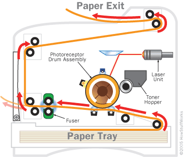
When a laser printer starts a print job, the first thing it does is apply a positive electrical charge to the drum unit. Afterwards, the laser system ‘writes’ the page image onto the drum with a negative charge, creating an electric “virtual negative” of the image.
The Toner The drum unit rotates, and as the image is written on it, it picks up toner, the laser printer equivalent of ink. The toner is positively charged, and so it sticks to the image that the laser drew. The paper presses against the drum, and receives the toner image.

The Fuser
When the paper first picks up the toner, the image is not set. Toner is a dry, dusty material, and it the electric charge cannot hold it strongly to the paper. In order to make the image permanent, the paper runs through the fuser, which heats it, and melts the toner onto the page. The paper exits the printer, and you have your print out.
How does a laser printer work with the toner?
The image below shows you how a laser printer works in conjuction with your toner cartridge. After you send a document to print - the paper travels through the printer, past the drum, toner and fuser unit and ends up as a printed page of text or graphics.


Courtesy:http://www.zinetic.co.uk

Hardwork Can Never Ever Fails..
Best Luck..

Saturday, November 10, 2012

Propogation Delay and Glitch

Propogation Delay:

Propagation delay is a time associated with any digital circuit and is the time between when an input to the circuit changes until that change propagates through the circuit and changes the output. Every digital gate (And, Or, Inverter,...) has its own propagation delay. For single gates this delay can be very short, maybe somewhere around nano seconds or shorter. But as the circuit grows larger and more components are put one after another, the delay increases too. Figure below shows the propagation delay effect of a simple inverter on its output where Tp is the propagation time:
In a more complex circuit every input can go through many different paths until it reaches the output. Every path in the circuit also has a different delay and for a single input, the propagation delay is the delay of the path with the longest delay because it takes that much time for that input to give a valid output. For a multiple input circuit, the propagation delay is equal to the maximum delay in the circuit. This is because if the output of the circuit is read shorter than the maximum delay, in some cases the output might not be valid and can result in false interpretations and actions.
The difference in propagation delay of different circuit paths can result in glitches on the output.

Glitch:

A glitch is called to an invalid and unpredicted output of a digital circuit that can be read by the next stage and result in a wrong action. Glitches happen mostly due to propagtion delays in a digital circuit. For example assume a circuit as below:
When input I=1, the output is 1 as one of the inputs to the OR gate is one. When I=0 also the output is 1 as the output of the inverter will be 1 going to the OR gate. So for both these cases the output should remain as 1. But let's see what happens when we assume some propagation delay for the inverter. Below you can see the signals to the circuit and the output:

You can see that when the input change from 1 to 0, it takes a short time for the inverter to provide a 1 at its output due to its propagation delay. Therefore for that short period of time both inputs to the OR gate are zero, resulting in a zero at the output of the OR gate. Then finally after the inverter output changes to 1, the OR gates output changes to one too.
This example shows happening of an unexpected zero ar the circuit. This is a glitch and can cause problem for the rest of the circuit as it will propagate into the next circuits and result in more and more glitches.

Ways to avoid glitch:

There are ways to avoid such glitches. One of the most practical ways is to put a timed gate such as a latch or a flip-flop to isolate the output of this circuit from the next circuit and allow the output to the next circuit only when it is valid and there are no glitches. The digital signal that allows the output of this circuit to pass through must wait for enough time since the inputs change until all the glitches pass, which would be more than the maximum propagation delay of the circuit. Then it can let the output of the circuit to be presented to the next stage.
The propagation delay of a circuit is an important factor on how fast the circuit can work. When one block of the circuit has a high delay, all the rest of the circuit will have to wait for this one block to provide a valid output.

Hardwork Can Never Ever Fails...
Best Luck...


Time Delay Relay circuits

       A special class of electromechanical relays called time-delay relays provide delayed action, either upon power-up or power-down, and are commonly denoted in ladder logic diagrams by "TD" or "TR" designations near the coil symbols and arrows on the contact symbols. Here is an example of a time-delay relay contact used in a motor control circuit:
In this circuit, the motor delays start-up until three seconds after the switch is thrown to the "Run" position, but will stop immediately when the switch is returned to the "Stop" position. The relay contact is referred to as normally-open, timed-closed, or NOTC. It is alternatively referred to as a normally-open, on-delay contact.

Time-delay relay contact type symbols and labels:


>>Normally-closed, on-delay
>>Normally-open, on-delay
>>Normally-open, off-delay
>>Normally-closed, off-delay

Practice Sum:

Time-delay relays are important circuit elements in many applications. Determine what each of the lamps will do in the following circuit when pushbutton Ä" is pressed for 10 seconds and then released.

Timing diagram:

ANS:


Hardwork Can Never Ever Fails...
Best Luck....

Thursday, November 01, 2012

PIC Animated Tutorials

Please click the Below link to get a collection of useful animations for the Peripheral Interface Controller (PIC)

Animation

Harvard vs Von Nuemann Architecture

Please click the below link to view a useful animation of the different architectures of Microprocessors/ DSP processors.

Animation

Wednesday, October 24, 2012

IEEE 802 Standards

IEEE 802 refers to a family of IEEE standards dealing with local area networks and metropolitan area networks.


NameDescriptionNote
IEEE 802.1Bridging (networking) and Network Management
IEEE 802.2Logic Link Controlinactive
IEEE 802.3Ethernet
IEEE 802.4Token busdisbanded
IEEE 802.5Defines the MAC layer for a Token Ringinactive
IEEE 802.6Metropolitan Area Network (Distributed Queue Dual Bus)disbanded
IEEE 802.7Broadband Local Area Network using Coaxial Cabledisbanded
IEEE 802.8Fiber Optic TAGdisbanded
IEEE 802.9Integrated Services LAN disbanded
IEEE 802.10Interoperable LAN Securitydisbanded
IEEE 802.11 a/b/g/nWireless LAN (WLAN) & Mesh (Wi-Fi certification)
IEEE 802.12100BaseVGdisbanded
IEEE 802.13Unused
IEEE 802.14Cable modemsdisbanded
IEEE 802.15Wireless Personal area Network
IEEE 802.15.1Bluetooth certification
IEEE 802.15.2IEEE 802.15 and IEEE 802.11 coexistence
IEEE 802.15.3High-Rate wireless PAN
IEEE 802.15.4Low-Rate wireless PAN (e.g., ZigBee, WirelessHART, MiWi, etc.)
IEEE 802.15.5Mesh networking for WPAN
IEEE 802.15.6Body area network
IEEE 802.16Broadband Wireless Access (WiMAX certification)
IEEE 802.16.1Local Multipoint Distribution Service
IEEE 802.17Resilient packet ring
IEEE 802.18Radio Regulatory TAG
IEEE 802.19Coexistence TAG
IEEE 802.20Mobile Broadband Wireless Access
IEEE 802.21Media Independent Handoff
IEEE 802.22Wireless Regional Area Network
IEEE 802.23Emergency Services Working Group
IEEE 802.24Smart Grid TAGNew (November, 2012)
IEEE 802.25Omni-Range Area Network
NETWORK BRIDGING

Network bridging describes the action taken by network equipment to allow two or more communication networks, or two or more network segments creating an aggregate network. Bridging is distinct from routing which allows the networks to communicate independently as separate networks. A network bridge is a network device that connects more than one network segment.

Monday, October 22, 2012

The Nuclear Power plant

The nuclear energy of the power plant is released from the atomic nucleus of a heavy element called uranium. Thus unlike a traditional power plant that consumes fossil fuels, a nuclear power plant consumes uranium. 

What actually happens to the uranium nuclei in a nuclear power plant? When a neutron collides with the nucleus of a uranium atom, the nucleus is split into two smaller nuclei in a process known as nuclear fission, releasing nuclear energy and emitting two or three neutrons. These released neutrons then collide with other uranium nuclei, producing further splitting and more energy. This continuous process of nuclear fission is known as chain reaction and a lot of energy is produced. A chain reaction is shown in the figure below.  

The Nuclear Chain Reaction


The nuclear power plant is divided into two main parts: the Nuclear Island and the Conventional Island. The Nuclear Island contains nuclear fuel in closed tubes packed together, collectively known as the reactor core. Nuclear energy is converted to heat energy in the reactor core. The Conventional Island is where heat energy received from the Nuclear Island is converted to electrical energy. Nuclear energy is converted to electrical energy in a nuclear power plant. The animation below will show you the inside of a nuclear power plant such as the Guangdong Daya Bay Nuclear Power Station.

What is Quantum tunneling?


Let's say you are throwing a rubber ball against a wall. You know you don't have enough energy to throw it through the wall, so you always expect it to bounce back. Quantum mechanics, however, says that there is a small probability that the ball could go right through the wall (without damaging the wall) and continue its flight on the other side! With something as large as a rubber ball, though, that probability is so small that you could throw the ball for billions of years and never see it go through the wall. But with something as tiny as an electron, tunneling is an everyday occurrence. 

Quantum tunneling is possible because of the wave-nature of matter. Confounding as it sounds, in the quantum world, particles often act likes waves of water rather than billiard balls. This means that an electron doesn't exist in a single place at a single time and with a single energy, but rather as a wave of probabilities.

What is Quantum Mechanics?

In the early 20th century some experiments produced results which could not be explained by classical physics (the science developed by Galileo Galilei, Isaac Newton, etc.). 

For instance, it was well known that electrons orbited the nucleus of an atom. However, if they did so in a manner which resembled the planets orbiting the sun, classical physics predicted that the electrons would spiral in and crash into the nucleus within a fraction of a second. 

Obviously that doesn't happen, or life as we know it would not exist. (Chemistry depends upon the interaction of the electrons in atoms, and life depends upon chemistry). 

Probability Density of electron in an Hydrogen Atom


That incorrect prediction, along with some other experiments that classical physics could not explain, showed scientists that something new was needed to explain science at the atomic level. 

Thus, quantum mechanics is the study of matter and radiation at an atomic level. 

For everyday things, which are much larger than atoms and much slower than the speed of light, classical physics does an excellent job. Plus, it is much easier to use than either quantum mechanics or relativity (each of which require an extensive amount of math). 

The d and s subs shells in the Quantum mechanics atom model


Every quantum particle is characterized by a wave function. In 1925 Erwin Schrödinger developed the differential equation which describes the evolution of those wave functions. By using Schrödinger's equation scientists can find the wave function which solves a particular problem in quantum mechanics.

The following are among the most important things which quantum mechanics can describe while classical physics cannot:
  • Discreteness of energy
  • The wave-particle duality of light and matter
  • Quantum tunneling
  • The Heisenberg uncertainty principle
  • Spin of a particle
Some funny facts! 


'It is impossible, absolutely impossible to explain it in any classical way'. 
Richard Feynman


[I can't accept quantum mechanics because] "I like to think the moon is there even if I am not looking at it. God does not play dice with the universe."
 Albert Einstein

"[T]he atoms or elementary particles themselves are not real; they form a world of potentialities or possibilities rather than one of things or facts." 
Werner Heisenberg


"Anyone not shocked by quantum mechanics has not yet understood it."
 Neils Bohr

"Nobody understands quantum mechanics."
Richard Feynman

Zener Vs Avalanche Breakdown

ZENER BREAKDOWN:

In Zener breakdown the electrostatic attraction between the negative electrons and a large positive voltage is so great that it pulls electrons out of their covalent bonds and away from their parent atoms. ie Electrons are transferred from the valence to the conduction band. In this situation the current can still be limited by the limited number of free electrons produced by the applied voltage so it is possible to cause Zener breakdown without damaging the semiconductor.

When the P & N regions are heavily doped, direct rupture of covalent bonds takes place because of the strong electric fields.

The new hole-electron pairs so created increase the reverse current in a reverse biased PN diode.

The increase in current takes place at a constant value of reverse bias typically below 6V for heavily doped diodes.

For lightly doped diodes, zener break down voltage becomes high and breakdown is then by Avalanche multiplication.


AVALANCHE BREAKDOWN:
 
Avalanche breakdown occurs when the applied voltage is so large that electrons that are pulled from their covalent bonds are accelerated to great velocities. These electrons collide with the silicon atoms and knock off more electrons. These electrons are then also accelerated and subsequently collide with other atoms. Each collision produces more electrons which leads to more collisions etc. The current in the semiconductor rapidly increases and the material can quickly be destroyed.

As the applied reverse bias increases, the field across the junction increases correspondingly.

Thermally generated carriers while traversing the junction acquire a large amount of kinetic energy from this field. As a result the velocity of these carrier increases. These electrons disrupt covalent bonds by colliding with immobile ions and create new hole-electron pairs.

These new carriers again acquire sufficient energy from the field and collide with other immobile ions, thereby generating further hole electron pairs. This process is cumulative in nature and results in generation of an avalanche of charge carriers with in a short time. This mechanism of carrier generation is known as Avalanche multiplication. This process results in flow of large amount of current at the same value of reverse bias. 

Usually the Avalanche Breakdown occurs above 6V. 


Sunday, October 14, 2012

Microwave Transmission


  • Microwave transmission refers to the technology of transmitting information or energy by the use of radio waves whose wavelengths are conveniently measured in small numbers of centimetre. 
  • Microwave radio spectrum ranges across frequencies of roughly 1.0 gigahertz (GHz) to 30 GHz. These correspond to wavelengths from 30 centimeters down to 1.0 cm.
  • Microwaves are widely used for point-to-point communications because their small wavelength allows conveniently-sized antennas to direct them in narrow beams, which can be pointed directly at the receiving antenna. This allows nearby microwave equipment to use the same frequencies without interfering with each other, as lower frequency radio waves do. 
  • Another advantage is that the high frequency of microwaves gives the microwave band a very large information-carrying capacity; the microwave band has a bandwidth 30 times that of all the rest of the radio spectrum below it.
  •  A disadvantage is that microwaves are limited to line of sight propagation; they cannot pass around hills or mountains as lower frequency radio waves can.

Applications:
  • Microwave radio transmission is commonly used in point-to-point communication systems on the surface of the Earth, in satellite communications, and in deep space radio communications. 
  • Other parts of the microwave radio band are used for radars, radio navigation systems, sensor systems, and radio astronomy.

Wednesday, October 10, 2012

What is War of Currents?

Why mostly the Power Distribution systems uses AC over DC?

Actually, at the time of development in Electrical Systems and Electrical Distribution, Both AC and DC were used for the Power Distribution.

AC Generator


Thomas Edison Promoted DC Power Distribution System and Nikola Tesla and George Westinghouse, promoted the AC Power Distribution System.
This is known as War of currents! (1880s)

Finally AC won over the DC Power Distribution System.


The main Reasons for use of AC in Power Distribution System are:

1. When Electricity passes through a Conductor, there is Transmission loss in the form of Heat. It is also known as Ohmic Loss.

Power Loss = I^2 Rt
Where I  = Current
           R = Resistance of the Conductor
            t = time

So if we transmit larger currents, the loss will be more.
However, in AC, there is a relation for the Transformers
I1V1=I2V2
ie, when the Voltage at one end of the transformed increases, Current decreases.
This is because, we have to keep the product of Current and Voltage constant.

So if we can transmit the Current at Higher Voltage, it will reduce the current through the Conductor and in effect the Ohmic Power loss will decrease.

2. Long distance Power Transmission is possible with Higher voltage. This can be easily achieved using the Transformers in AC, However Stepping up and Stepping Down using Transformers are not possible in DC.

AC Power Distribution


However there are some advantages for DC over AC

DC power maintains a constant direction of current. One advantage of DC power is there is no reactance in the line. 

This allows higher power transfer capability, higher capacity utilization of generators, and less of a voltage drop along the line. 

DC also has a lower line resistance than AC because of the “skin effect” in AC. This is when charge is carried mostly near the outside of the wire.

In the DC system, power is just the real component. This means that the transmission system operator need not worry about the sufficiency of reactive power to maintain the security and stability of the system.

In DC, there is no frequency, so generators connected to the transmission grid do not need to be synchronized.

The DC system does not introduce susceptance along the line thus removing the effect of changing current and over voltages in the system.

Analysis of DC systems only involves real numbers, while AC systems involve complex numbers. (Think about a world without AC; How easy will be the calculations in Electrical Engineering :-) )

A good Resource for studying the AC Theory is available Here

Tuesday, October 09, 2012

Why all Digital Electronics Circuits use DC and Not AC?

The question will be little confusing.
But the answer is simple.

AC Vs DC


In Digital Electronics, Gates are the basic Elements.
Actually this Gates are made up of Transistors.

NAND gate using Transistors


Transistors are working as a Switch in Digital Electronics.

Transistor as a Switch


ie, When control signal is present, Transistor is ON, otherwise Transistor is OFF.

Now, What is this Control Signal?

That is the Signal Applied to the Base of the Transistor.

The Switch must be ON till the control signal is present and the Switch must be OFF till the control signal is absent.

Switch with Control Terminal


Now consider applying AC signal as the control signal to the Base of the Transistor.

The AC signal will vary from Positive peak to Negative peak going through the 0V.

So how can we keep the Transistor ON and OFF as per our requirement?
It is not possible.

Now consider DC. It is Direct current and it is constant in value.
So if we apply DC to the Base of the Transistor as a control signal, we can keep the Transistor ON of OFF as per our wish.

That is In digital Electronics, We need only HIGH signal and LOW signal, not the intermediate values.
Hence we cannot use AC in Digital.

Now consider Transistor working as an AMPLIFIER.
Here also, the transistor is working in DC (Power supply of the Transistor is DC), but the input is an AC signal.

Transistor as an Amplifier

Thus Amplification of AC signal is just an application of the Transistor and that doesn't mean that the Transistor is working in AC.

Why cant we power the Transistor with AC?
We can apply AC as a Power supply to the Transistor.
But the transistor will not give the desired operation.

Biasing of Transistor (a) NPN  (b) PNP


Because, for acting as a Switch or Amplifier, the transistor should be biased.
In order to keep the transistor in constant Biasing conditions, we need Constant current. ie DC.

If we apply AC as a power supply to the transistor, the Biasing conditions of the Transistor will be varying in each cycle of the AC signal.

Hence the transistor will not work properly.
This is the reason why we convert the AC signals into DC using Rectifiers in the Power supply section of the Electronic Devices.

(We can apply the same principle to MOSFET also.
MOSFET are used as switches in Digital Electronics as Switches.
Working principle of MOSFET is same as that of the Transistor.
However, MOSFET is a Voltage controlled Device, but Transistor is a Current controlled Device.)