A boost converter is a DC-to-DC power converter with an output voltage greater than its input voltage. It is a class of switched-mode power supply (SMPS) containing at least two semiconductor switches (a diode and a transistor) and at least one energy storage element, a capacitor or inductor. The boost converter is also called as step-up converter.
OPERATING PRINCIPLE:
The key principle that drives the boost converter is the tendency of an inductor to resist changes in current. In a boost converter, the output voltage is always higher than the input voltage.
In the above figure, when the switch is turned-ON, the current flows through the inductor and energy is stored in it. When the switch is turned-OFF, the stored energy in the inductor tends to collapse and its polarity changes such that it adds to the input voltage. Thus, the voltage across the inductor and the input voltage are in series and together charge the output capacitor to a voltage higher than the input voltage.
The basic principle of a Boost converter consists of 2 distinct states in above figure,
So it is not discontinuous as in the buck converter and the requirements on the input filter are relaxed compared to a buck converter.
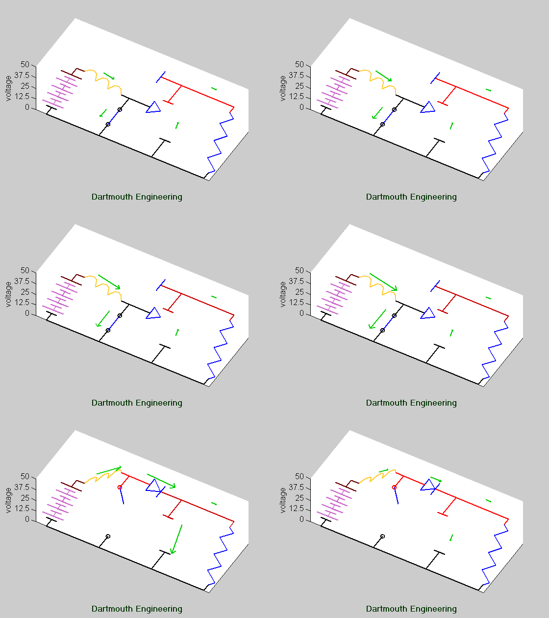
Below animation shows the operating of the boost converter,

 |
| Basic schematic of boost converter. |
Power for the boost converter come from any suitable DC sources, such as batteries, solar panels, rectifiers and DC generators. A process that changes one DC voltage to a different DC voltage is called DC to DC conversion. A boost converter is a DC to DC converter with an output voltage greater than the source voltage.
OPERATING PRINCIPLE:
The key principle that drives the boost converter is the tendency of an inductor to resist changes in current. In a boost converter, the output voltage is always higher than the input voltage.
In the above figure, when the switch is turned-ON, the current flows through the inductor and energy is stored in it. When the switch is turned-OFF, the stored energy in the inductor tends to collapse and its polarity changes such that it adds to the input voltage. Thus, the voltage across the inductor and the input voltage are in series and together charge the output capacitor to a voltage higher than the input voltage.
 |
| Configurations of boost converter depends on the switch S. |
The basic principle of a Boost converter consists of 2 distinct states in above figure,
- in the On-state, the switch S is closed, resulting in an increase in the inductor current;
- in the Off-state, the switch is open and the only path offered to inductor current is through the flyback diode D, the capacitor C and the load R. This results in transferring the energy accumulated during the On-state into the capacitor.
So it is not discontinuous as in the buck converter and the requirements on the input filter are relaxed compared to a buck converter.
Below animation shows the operating of the boost converter,


What a wonderfull post! thank you... read with pleasure!
ReplyDeleteBest Salesforce Training Institute in Noida
Best Salesforce Admin Training Institute in Noida