Friday, August 31, 2012

CAR ANTI - THEFT GUARD

Here is an easy-to-build car anti-theft guard. The circuit, shown in Fig. 1, is simple and easy to understand. When key-operated switch S2 of the car is turned on, 12V DC supply from the car battery is extended to the entire circuit through polarity-guard diode D5. Blinking LED1 flashes to indicate that the guard circuit is enabled. It works off 12V power supply along with current-limiting resistor R4 in series.


Fig. 1: Circuit of car anti-theft guard 
When the car door is closed, door switch S1 is in 'on' position and 12V power supply is available across resistor R1, which prevents transistor T1 from conducting. In this position, anti-theft guard circuit is in sleep mode.

When someone opens the car door, switch S1 becomes 'off' as shown in Fig. 2. As a result, transistor T1 conducts to fire relay-driver SCR1 (BT169) after a short delay introduced by capacitor C1. Electromagnetic relay RL1 energises and its N/O contact connects the power supply to piezobuzzer PZ1, which starts sounding to indicate that someone is trying to steal your car. To reset the circuit, turn off switch S2 using car key. This will cut-off the power supply to the circuit and stop the buzzer sound.


Fig. 2: Wiring diagram for door switch
Assemble the circuit on a general-purpose PCB and house in a small box. Connect switch S1 to the car door and keep piezobuzzer PZ1 at an appropriate place in the car.

Thursday, August 30, 2012

Binary to Gray Code Converter

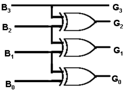
Gray code equivalent of the given binary number is computed as follows:
g3 = b3
g2 = b3 ⊕ b2
g1 = b2 ⊕ b1
g0 = b1 ⊕ b0
binary to gray code converter can be implemented using XOR gates. For n input, n-1 gates are required. As shown in the image below for 4 inputs, 3 XOR gates are used:

CONVERTING BETWEEN GRAY AND BINARY CODES ANIMATION

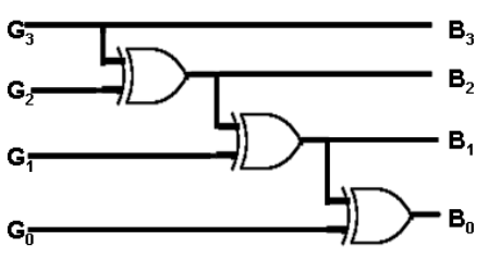
Gray to Binary Code Converter

Binary code equivalent of the given gray number is computed as follows:b3 = g3b2 = b3 ⊕ g2b1 = b2 ⊕ g1b0 = b1 ⊕ g0gray to binary code converter can be implemented using XOR gates. For n input, n-1 gates are required. As shown in the image below for 4 inputs, 3 XOR gates are used:

What's a Smith chart?


       What is a Smith chart? It's really just a plot of complex reflection overlaid with an impedance and/or admittance grid referenced to a 1-ohm characteristic impedance. That's it! Transmission coefficient, which equals unity plus reflection coefficient, may also be plotted (see below). You can find books and articles describing how a Smith chart is a graphical representation of the transmission line equations and the mathematical reasons for the circles and arcs, but these things don't really matter when you need to get the job done. What matters is knowing the basics and how to use them, like always.
The Smith chart contains almost all possible impedances, real or imaginary, within one circle. All imaginary impedances from - infinity to + infinity are represented, but only positive real impedances appear on the "classic" Smith chart. Yes, it is possible to go outside the Smith chart "unity" circle, but only with an active device because this implies negative resistance.
       One thing you give up when plotting reflection coefficients on a Smith chart is a direct reading of a frequency axis. Typically, plots that are done over any frequency band have markers calling out specific frequencies.
Why use a Smith chart?  It's got all those funny circles and arcs, and good ol' rectangular plots are much better for displaying things like VSWR, transmission loss, and phase, right? Perhaps sometimes a rectangular plot is better, but a Smith chart is the RF engineer's best friend! It's easy to master, and it adds an air of "analog coolness" to presentations, which will impress your friends, if not your dates! A master in the art of Smith-charting can look at a thoroughly messed up VSWR of a component or network, and synthesize two or three simple networks that will impedance-match the circuit in his head!

Impedance and admittance

          A quick refresher on the basic quantities that have units of ohms or its reciprocal, Siemens (sometimes called by its former name, mhos), is helpful since many of them will be referenced below. We all think of resistance (R) as the most fundamental of these quantities, a measure of the opposition to current flow that causes a potential drop, or voltage, according to Ohms Law: V=I*R. By extension, impedance (Z) is the steady state AC term for the combined effect of both resistance and reactance (X), where Z=R+jX. (X=jwL for an inductor, and X=1/jwC for a capacitor, where w is the radian frequency or 2*pi*f.) Generally, Z is a complex quantity having a real part (resistance) and an imaginary part (reactance).
We often think in terms of impedance and its constituent quantities of resistance and reactance. These three terms represent "opposition" quantities and are a natural fit for series-connected circuits where impedances add together. However, many circuits have elements connected in parallel or "shunt" that are a natural fit for the "acceptance" quantity of admittance (Y) and its constituent quantities of conductance (G) and susceptance (B), where Y=G+jB. (B=jwC for a capacitor, and B=1/jwL for an inductor.) Admittances add together for shunt-connected circuits. Remember that Y=1/Z=1/(R+jX), so that G=1/R only if X=0, and B=-1/X only if R=0.
        When working with a series-connected circuit or inserting elements in series with an existing circuit or transmission line, the resistance and reactance components are easily manipulated on the "impedance" Smith chart. Similarly, when working with a parallel-connected circuit or inserting elements in parallel with an existing circuit or transmission line, the conductance and susceptance components are easily manipulated on the "admittance" Smith chart. The "immittance" Smith chart simply has both the impedance and admittance grids on the same chart, which is useful for cascading series-connected with parallel-connected circuits.

Wednesday, August 29, 2012

Fleming’s Left Hand Rule and the Motor Effect


When a wire carrying an electric current is moved in a magnetic field of a magnet the magnetic field induced by the wire reacts with the magnetic field of the magnet causing the wire to move outwards. Fleming's left hand rule helps you to predict the movement.

First finger - direction of magnetic field (N-S)
SeCond finger - direction of current (positive to negative)
ThuMb - movements of the wire

When a coil of wire carrying a current is placed in a magnetic field the coil turns.
This is called the motor effect.


animation of flemings rule

Saturday, August 25, 2012

How Does an Air Conditioner Work?


Air conditioners and refrigerators work the same way. Instead of cooling just the small, insulated space inside of a refrigerator, an air conditioner cools a room, a whole house, or an entire business.

Air conditioners use chemicals that easily convert from a gas to a liquid and back again. This chemical is used to transfer heat from the air inside of a home to the outside air.

The machine has three main parts. They are a compressor, a condenser and an evaporator. The compressor and condenser are usually located on the outside air portion of the air conditioner. The evaporator is located on the inside the house, sometimes as part of a furnace. That's the part that heats your house.

The working fluid arrives at the compressor as a cool, low-pressure gas. The compressor squeezes the fluid. This packs the molecule of the fluid closer together. The closer the molecules are together, the higher its energy and its temperature.

The working fluid leaves the compressor as a hot, high pressure gas and flows into the condenser. If you looked at the air conditioner part outside a house, look for the part that has metal fins all around. The fins act just like a radiator in a car and helps the heat go away, or dissipate, more quickly.

When the working fluid leaves the condenser, its temperature is much cooler and it has changed from a gas to a liquid under high pressure. The liquid goes into the evaporator through a very tiny, narrow hole. On the other side, the liquid's pressure drops. When it does it begins to evaporate into a gas.

As the liquid changes to gas and evaporates, it extracts heat from the air around it. The heat in the air is needed to separate the molecules of the fluid from a liquid to a gas.

The evaporator also has metal fins to help in exchange the thermal energy with the surrounding air.

By the time the working fluid leaves the evaporator, it is a cool, low pressure gas. It then returns to the compressor to begin its trip all over again.

Connected to the evaporator is a fan that circulates the air inside the house to blow across the evaporator fins. Hot air is lighter than cold air, so the hot air in the room rises to the top of a room.

There is a vent there where air is sucked into the air conditioner and goes down ducts. The hot air is used to cool the gas in the evaporator. As the heat is removed from the air, the air is cooled. It is then blown into the house through other ducts usually at the floor level.

This continues over and over and over until the room reaches the temperature you want the room cooled to. The thermostat senses that the temperature has reached the right setting and turns off the air conditioner. As the room warms up, the thermostat turns the air conditioner back on until the room reaches the temperature.

Types of Air Conditioners we supply
There are basically 3 types of air conditioners we supply, the portable air conditioners, split air conditioning system and the window air conditioning .

Our portable air conditioners are ideal for short term cooling and being mobile they can be moved from one place to another. They do not require an outdoor unit and installation. You simply plug the 13amp plug provided with the unit, attach the hose provided out of a window or door and you can enjoy the cool air. More about portable air conditioners .

The split air conditioning systems are sometimes known as "fixed air conditioning systems". You install the units to a fixed wall, connect the indoor unit to the outdoor unit. Therefore, this is not mobile. But the advantages of a split air conditioning system compared with a portable air conditioner is that it is quiet, more efficient and tidy as it does not take up your room floor space. More about split air conditioning systems.

The window air conditioning is fitted in the wall so that the back of the window air conditioning is facing the exterior whilst the front of the window air conditioning is facing the internal room

Friday, August 24, 2012

Why we go for Digital?


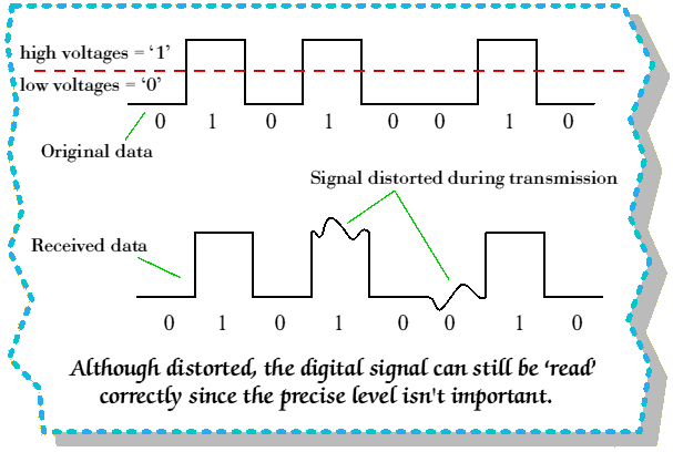
  • One advantage of digital circuits when compared to analog circuits is that signals represented digitally can be transmitted without degradation due to noise. For example, a continuous audio signal, transmitted as a sequence of 1s and 0s, can be reconstructed without error provided the noise picked up in transmission is not enough to prevent identification of the 1s and 0s. An hour of music can be stored on a compact disc as about 6 billion binary digits.

  • In a digital system, a more precise representation of a signal can be obtained by using more binary digits to represent it. While this requires more digital circuits to process the signals, each digit is handled by the same kind of hardware. In an analog system, additional resolution requires fundamental improvements in the linearity and noise characteristics of each step of the signal chain.
  • Computer-controlled digital systems can be controlled by software, allowing new functions to be added without changing hardware. Often this can be done outside of the factory by updating the product's software. So, the product's design errors can be corrected after the product is in a customer's hands.
  • Information storage can be easier in digital systems than in analog ones. The noise-immunity of digital systems permits data to be stored and retrieved without degradation. In an analog system, noise from aging and wear degrade the information stored. In a digital system, as long as the total noise is below a certain level, the information can be recovered perfectly.

Finally one question to the readers

Is reality digital or analog?

What are Digital Signal Processors?

Digital Signal Processors (DSPs) take real-world signals like voice, audio, video, temperature, pressure, or position that have been digitized and then mathematically manipulate them. 

A DSP is designed for performing mathematical functions like "add", "subtract", "multiply" and "divide" very quickly.

Signals need to be processed so that the information that they contain can be displayed, analyzed, or converted to another type of signal that may be of use. 

In the real-world, analog products detect signals such as sound, light, temperature or pressure and manipulate them. Converters such as an Analog-to-Digital converter then take the real-world signal and turn it into the digital format of 1's and 0's. 

From here, the DSP takes over by capturing the digitized information and processing it. It then feeds the digitized information back for use in the real world. It does this in one of two ways, either digitally or in an analog format by going through a Digital-to-Analog converter. All of this occurs at very high speeds.

DSP in MP3 Audio Player


To illustrate this concept, the diagram above shows how a DSP is used in an MP3 audio player. 

During the recording phase, analog audio is input through a receiver or other source. This analog signal is then converted to a digital signal by an analog-to-digital converter and passed to the DSP. 

The DSP performs the MP3 encoding and saves the file to memory. During the playback phase, the file is taken from memory, decoded by the DSP and then converted back to an analog signal through the digital-to-analog converter so it can be output through the speaker system. 

(Courtesy: www.analog.com)

IMAGE FORMATION IN PLANE MIRROR

The precise direction of the sight line depends on the location of the object, the location of the person, and the type of mirror. Yet all of the lines of sight, regardless of their direction, will pass through the image location. In fact, the image location is defined as the location where it seems to every observer as though light is coming from. Since all people see reflected rays of light as they sight at an image in the mirror, then the image location must be the intersection point of these reflected rays.
 In the animation above, an object is positioned in front of a plane mirror. The plane mirror will produce an image of the object on the opposite side of the mirror. The distance from the object to the mirror equals the distance from the image to the mirror. Any person viewing this image must sight at this image location. The animation depicts the path of several rays of light from the object to the mirror. This light subsequently reflects such that observers could sight along a line of sight and view the image. Different people might sight from different locations; yet each person would sight at the same image location. As seen in the animation, the image location is the intersection point of all the reflected rays.

REFLECTION OF LIGHT

When light rays traveling is a medium reaches the boundary of other medium, they turn back to the first medium. This phenomenon of turning back of light into the same medium after striking the boundary of other medium is called Reflection of Light.


LAWS OF REFLECTION

1. The angle of incident is equal to the angle of reflection.
2. The incident ray, the reflected ray and the normal lie on the same plane. 


REGULAR REFLECTION

When a beam pass of parallel light rays is incident on a smooth and plane surface, the reflected rays will also be parallel. This type of reflection is called Regular Reflection.


IRREGULAR REFLECTION

When a beam of parallel light rays is scattered in all directions. Therefore the parallel rays incident on the surface will reflect in different directions. This is also called Diffuse Reflection.


Generations in mobile communication


1G:

The first generation of systems for mobile telephony was analog, circuit switched, and it only carried voice traffic. The analog phones used in 1G were less secure and prone to interference where the signal is weak. Analog systems include AMPS, NMT and ETACS.


2G:

The second-generation phones cover all speech into digital code, resulting in a clear signal that can be encrypted for security. Most also include some kind of messaging, as well as support for Centrex style services such as voice mail and caller ID. 


The most popular is GSM (Global System for Mobile Communications), but several others are used around the world. They can send data, but usually at less than 10 kilobits per second (Kbps); by comparisons, most modems achieve a real speed of atleast 30 Kbps. 

2G networks include GSM, D-AMPS (TDMA) and CDMA. 2G networks can support SMS applications.


2.5 G:

The successor of the 2G technology is the 2.5G. 2.5 G supports higher data speeds. The term 2.5G also applies to technology such as WAP (Wireless Application Protocol), which uses a version of the web to fit into a mobile phone’s slow data rate and small screen. 

2.5G networks include EDGE (Enhanced Data Rates) and GPRS (General Packet Radio Service). These networks support WAP, MMS, SMS mobile games, and search and directory. Though MMS was introduced in the 2.5G, it really gained its momentum and fame only with the introduction of 3G.


3G:

As the use of 2G phones became more widespread and people began to utilize mobile phones in their daily lives, it became clear that demand for data services (such as access to the internet) was growing. Furthermore, experience from fixed broadband services showed there would also be an ever increasing demand for greater data speeds. The 2G technology was nowhere near up to the job, so the industry began to work on the next generation of technology known as 3G. 

The main technological difference that distinguishes 3G technology from 2G technology is the use of packet switching rather than circuit switching for data transmission.


4G

By 2009, it had become clear that, at some point, 3G networks would be overwhelmed by the growth of bandwidth-intensive applications like streaming media. Consequently, the industry began looking to data-optimized 4th-generation technologies, with the promise of speed improvements up to 10-fold over existing 3G technologies. 

The first two commercially available technologies billed as 4G were the WiMAX standard and the LTE standard.

5G is not officially used for any specification or official document yet made public by telecommunication companies or standardization bodies such as 3GPP, WiMAX Forum, or ITU-R.


Comparison of different Generations.

Wednesday, August 22, 2012

ELECTROMAGNETIC SPECTRUM


The electromagnetic spectrum is the distribution of electromagnetic radiation according to energy (or according to frequency or wavelength).


The Spectrum of Visible Light

The visible part of the spectrum may be further subdivided according to color, with red at the long wavelength end and violet at the short wavelength end, as illustrated (schematically) in the following figure.


Tuesday, August 21, 2012

Channel allocation in Cellular System

Channel allocation deals with the allocation of channels to cells in a cellular network. Once the channels are allocated, cells may then allow users within the cell to communicate via the available channels. 

Channels in a wireless communication system typically consist of time slots, frequency bands and/or CDMA pseudo noise sequences, but in an abstract sense, they can represent any generic transmission resource. 

There are three major categories for assigning these channels to cells (or base-stations). They are
  • Fixed Channel Allocation, 
  • Dynamic Channel Allocation and 
  • Hybrid Channel Allocation which is a combination of the first two methods.
Fixed Channel Allocation
        Fixed Channel Allocation (FCA) systems allocate specific channels to specific cells. This allocation is static and can not be changed. For efficient operation, FCA systems typically allocate channels in a manner that maximizes frequency reuse. Thus, in a FCA system, the distance between cells using the same channel is the minimum reuse distance for that system. 

The problem with FCA systems is quite simple and occurs whenever the offered traffic to a network of base stations is not uniform. Consider a case in which two adjacent cells are allocated N channels each. There clearly can be situations in which one cell has a need for N+k channels while the adjacent cell only requires N-m channels (for positive integers k and m). In such a case, k users in the first cell would be blocked from making calls while m channels in the second cell would go unused. Clearly in this situation of non-uniform spatial offered traffic, the available channels are not being used efficiently.


Dynamic Channel Allocation
In DCA systems, no set relationship exists between channels and cells. Instead, channels are part of a pool of resources. Whenever a channel is needed by a cell, the channel is allocated under the constraint that frequency reuse requirements can not be violated. There are two problems that typically occur with DCA based systems.
  • First, DCA methods typically have a degree of randomness associated with them and this leads to the fact that frequency reuse is often not maximized unlike the case for FCA systems in which cells using the same channel are separated by the minimum reuse distance. 
  • Secondly, DCA methods often involve complex algorithms for deciding which available channel is most efficient. These algorithms can be very computationally intensive and may require large computing resources in order to be real-time. 
Hybrid Channel Allocation Schemes
The third category of channel allocation methods includes all systems that are hybrids of fixed and dynamic channel allocation systems. 

Channel Borrowing is one of the most straightforward hybrid allocation schemes. Here, channels are assigned to cells just as in fixed allocation schemes. If a cell needs a channel in excess of the channels previously assigned to it, that cell may borrow a channel from one of its neighboring cells given that a channel is available and use of this channel won't violate frequency reuse requirements.

Monday, August 20, 2012

Walkie-Talkies

What is a walkie-talkie?

Walkie-talkies are a portable radio which is used to communicate on a shared frequency band.Each unit contains a transmitter ,receiver,antenna,loudspeaker.By clicking the push-to-talk it enables the microphone and thus the conversation takes place.More sophisticated walkie-talkies contain seperate loudspeakers and microphones.

  1. Antenna: Sends and receives radio waves.
  2. Lcd display:It Shows channel number, remaining battery life, and so on.
  3. Monitor: It can be also used as an monitoring device.hence,it can be used as a listening device.
  4. Menu select buttons (marked with plus and minus symbols).
  5. Menu button: We can change the functions .And it is used to lock the keypad.
  6. Loudspeaker.
  7. Push-to-talk (PTT) button.
  8. On/off switch and volume control.
  9. LED: indicator light shows when channels are busy.
  10. Microphone: Unlike some models, this walkie-talkie has a separate loudspeaker and microphone.
  11. Transmit call tone: This sends a tone signal to other radios on the same channel alerting them that you want to talk.

Who invented the walkie-talkie?

Walkie-talkies (originally called two-way radios or "pack sets") were invented in 1937 by Canadian Donald Hings (1907–2004) and, around the same time, by American inventor Alfred Gross (1918–2000). Both men saw their inventions developed for military use during World War II; both went on to devise numerous other inventions: Gross is credited with inventing pagers, which were a popular way of staying in touch on the move before cellphones became ubiquitous, while Hings developed numerous improvements to radio, radar, magnetic ground-surveying devices, and equipment for measuring air pollution (he has 39 different inventions listed at the US Patent and Trademark Office).


Hardwork Can Never Ever Fails...
Best Luck..


Saturday, August 18, 2012

Resistors

Resistor

what is a resistor?

A resistor is anything that electricity can not travel through easily. When electricity is forced through a resistor, often the energy in the electricity is changed into another form of energy, such as light or heat. The reason a light bulb glows is that electricity is forced through tungsten, which is a resistor. The energy is released as light and heat.
A conductor is the opposite of a resistor. Electricity travels easily and efficiently through a conductor, with almost no other energy released as it passes.

A resistor placed at the exterior of a spacecraft can release extra electrical energy into space as heat.

Types of resistors

1. CARBON FILM

    The most popular resistor type. This resistor made by depositing a carbon film onto a small ceramic cylinder. A small spiral groove cut into the film controls the amount of carbon between the leads, hence setting the resistance. Such resistors show excellent reliability, excellent solderability, noise stability, moisture stability, and heat stability. Typical power ratings range from 1/4 to 2 W. Resistances range from about 10 Ohm to 1 MOhm, with tolerances around 5 percent.

Typically yellow or tan jacket, peanut shape , 4 band code

CARBON COMPOSITION

This type is also popular. Its made from a mixture of carbon powder and glue like binder. To increase the resistance, less carbon is added. These resistors show predictable performance, low inductance, and low capacitance. Power ratings range from about 1/4 to 2 W. Resistances range from 1 Ohm to about 100 MOhm, with tolerances around +/- 5 percent.


Typically brown jacket, straight cylinder shape, 5 band code

METAL OXIDE FILM

This type is general purpose resistor. It uses a ceramic core coated with a metal oxide film. These resistors are mechanically and electrically stable and readable during high temperature operation. They contain a special paint on their outer surfaces making them resistant to flames, solvents, heat, and humidity. Typical resistances range from 1 Ohm to 200 kOhm, with typical tolerances of +/- 5 percent. 


Usually blue or grey color, 4 band code

PRECISION METAL FILM

 This type is very accurate, ultra low noise resistor. It uses a ceramic substrate coated with a metal film, all encased in an epoxy shell. These resistors are used in precision devices, such as test instruments, digital and analog devices, and audio and video devices. Resistances range from about 10 Ohm to 2 MOhm, with power rating from 1/4 to about 1/2 W, and tolerances of +/- 1 percent.


Typical blue color, 5 band code

PRECISION WIRE WOUND

The precision wire wound resistor is a highly accurate resistor (within 0.005%) with a very low TCR. A TCR of as little as 3ppm/o C can be achieved. However these components are too expensive for general use and are normally used in highly accurate dc applications.


HIGH POWER WIRE WOUND

These resistors are used for high power applications. Types include vitreous enamel coated, cement, and aluminum housed wire wound resistors. Resistive elements are made from a resistive wire that is coiled around a ceramic cylinder. These are the most durable of the resistors, with high heat dissipation and high temperature stability. Resistances range from 0.1 Ohm to  about 150 kOhm, with power ratings from around 2 W to as high as 500 W, or more.

Buy High power wire wound resistor 1R 200W

VARIABLE RESISTORS

Variable resistors provide varying degrees of resistance that can be set with the turn of a knob. Special kinds of variable resistors include potensiometers, rheostats, and trimmers. Potensiometers and rheostats are essentially the same thing, but rheostats are used specially for high power AC electricity, whereas potensiometers typically are used with lower level DC electricity. Both potensiometers and rheostats are designed for frequent adjustment. Trimmers, on the other hand, are miniature potensiometers that are adjusted infrequently and usually come with pins that can be inserted into pcb. They are used for fine tuning circuits (eg. : fine tuning a circuit that goes astray as it ages), and they are usually hidden within a circuits enclosure box. Variable resistors come with 2 or 3 terminals. There are 2 kinds of taper, ie. : linear tapered and nonlinear tapered (logarithmic). The 'taper' describes the way in which the resistance changes as the control knob is twisted. Linear taper usually has coded as 'A' while nonlinear tapes has coded as 'B'.


Color coding


Black Brown Red Orange Yellow Green Blue Violet Grey White  

How to remember?

BROof  Great  Britain has a Very Good Wife

Diodes


How a radio works?

"Radio waves" transmit music, conversations, pictures and data invisibly through the air, often over millions of miles -- it happens every day in thousands of different ways! Even though radio waves are invisible and completely undetectable to humans, they have totally changed society. Whether we are talking about a cell phone, a baby monitor, a cordless phone or any one of the thousands of other wireless technologies, all of them use radio waves to communicate.

Technologies that depends on radio waves:

  • AM and FM radio broadcasts
  • Cordless phones
  • Garage door openers
  • Wireless networks
  • Radio-controlled toys
  • Television broadcasts
  • Cell phones
  • GPS receivers
  • Ham radios
  • Satellite communications
  • Police radios
  • Wireless clocks

The Simplest Radio:

Radio can be incredibly simple, and around the turn of the century this simplicity made early experimentation possible for just about anyone.
Here a small experiment:
By tapping the terminals of a 9-volt battery with a coin, you can create radio waves that an AM radio can receive!


  • Take a fresh 9-volt battery and a coin.
  • Find an AM radio and tune it to an area of the dial where you hear static.
  • Now hold the battery near the antenna and quickly tap the two terminals of the battery with the coin (so that you connect them together for an instant).
  • You will hear a crackle in the radio that is caused by the connection and disconnection of the coin.
Your battery/coin combination is a radio transmitter! It's not transmitting anything useful (just static), and it will not transmit very far (just a few inches, because it's not optimized for distance). But if you use the static to tap out Morse code, you can actually communicate over several inches with this crude device!

A (Slightly) More Elaborate Radio:

If you want to get a little more elaborate, use a metal file and two pieces of wire. Connect the handle of the file to one terminal of your 9-volt battery. Connect the other piece of wire to the other terminal, and run the free end of the wire up and down the file. If you do this in the dark, you will be able to see very small 9-volt sparks running along the file as the tip of the wire connects and disconnects with the file's ridges. Hold the file near an AM radio and you will hear a lot of static.

In the early days of radio, the transmitters were called spark coils, and they created a continuous stream of sparks at much higher voltages (e.g. 20,000 volts). The high voltage created big fat sparks like you see in a spark plug, and they could transmit farther. Today, a transmitter like that is illegal because it spams the entire radio spectrum, but in the early days it worked fine and was very common because there were not many people using radio waves.

Radio Basics: The Parts

All radios today, however, use continuous sine waves to transmit information (audio, video, data). The reason that we use continuous sine waves today is because there are so many different people and devices that want to use radio waves at the same time.
Each different radio signal uses a different sine wave frequency, and that is how they are all separated.
Any radio setup has two parts:
  • The transmitter
  • The receiver
The transmitter takes some sort of message (it could be the sound of someone's voice, pictures for a TV set, data for a radio modem or whatever), encodes it onto a sine wave and transmits it with radio waves. The receiver receives the radio waves and decodes the message from the sine wave it receives. Both the transmitter and receiver use antennas to radiate and capture the radio signal.

 Radio Basics: Real-life Examples

  • Modulation: Amplitude Modulation (AM)
  • Frequency range: 49 MHz
  • Number of frequencies: 1 or 2
  • Transmitter power: 0.25 watts 
A cell phone is also a radio and is a much more sophisticated device A cell phone contains both a transmitter and a receiver, can use both of them simultaneously, can understand hundreds of different frequencies, and can automatically switch between frequencies. Here are some of the important characteristics of a typical analog cell phone:
  • Modulation: Frequency Modulation (FM)
  • Frequency range: 800 MHz
  • Number of frequencies: 1,664 (832 per provider, two providers per area)
  • Transmitter power: 3 watts  
 Hardwork Can Never Ever Fails...
Best Luck...


A quick tour on Bluetooth

What is Bluetooth ?

­Bluetooth takes small-area networking to the next level by removing the need for user intervention and keeping transmission power extremely low to save battery power.

How its creates connection?

To Describe,let us consider the following :

You're on your Bluetooth-enabled cell-phoned, standing outside the door to your house. You tell the person on the other end of the line to call you back in five minutes so you can get in the house and put your stuff away. As soon as you walk in the house, the map you received on your cell phone from your car's Bluetooth-enabled GPS system is automatically sent to your Bluetooth-enabled computer, because your cell phone picked up a Bluetooth signal from your PC and automatically sent the data you designated for transfer. Five minutes later, when your friend calls you back, your Bluetooth-enabled home phone rings instead of your cell phone. The person called the same number, but your home phone picked up the Bluetooth signal from your cell phone and automatically re-routed the call because it realized you were home. And each transmission signal to and from your cell phone consumes just 1 milliwatt of power, so your cell phone charge is virtually unaffected by all of this activity. 

Bluetooth wireless PC card:

Bluetooth is essentially a networking standard that works at two levels:

  • It provides agreement at the physical level -- Bluetooth is a radio-frequency standard.
  • It provides agreement at the protocol level, where products have to agree on when bits are sent, how many will be sent at a time, and how the parties in a conversation can be sure that the message received is the same as the message sent.
The big draws of Bluetooth are that it is wireless, inexpensive and automatic.
The other way to get around wire is Infrared communication.Still it has two problem.
1.Line of sight
2.One to One technology.

Bluetooth is intended to get around the problems that come with infrared systems. The older Bluetooth 1.0 standard has a maximum transfer speed of 1 megabit per second (Mbps), while Bluetooth 2.0 can manage up to 3 Mbps. Bluetooth 2.0 is backward-compatible with 1.0 devices. 


How Bluetooth Operates?


Bluetooth networking transmits data via low-power radio waves. It communicates on a frequency of 2.45 gigahertz (actually between 2.402 GHz and 2.480 GHz, to be exact). This frequency band has been set aside by international agreement for the use of industrial, scientific and medical devices (ISM).
A number of devices that you may already use take advantage of this same radio-frequency band

One of the ways Bluetooth devices avoid interfering with other systems is by sending out very weak signals of about 1 milliwatt. By comparison, the most powerful cell phones can transmit a signal of 3 watts. The low power limits the range of a Bluetooth device to about 10 meters (32 feet), cutting the chances of interference between your computer system and your portable telephone or television. Even with the low power, Bluetooth doesn't require line of sight between communicating devices. The walls in your house won't stop a Bluetooth signal, making the standard useful for controlling several devices in different rooms. 
Bluetooth can connect up to eight devices simultaneously. With all of those devices in the same 10-meter (32-foot) radius, you might think they'd interfere with one another, but it's unlikely. Bluetooth uses a technique called spread-spectrum frequency hopping that makes it rare for more than one device to be transmitting on the same frequency at the same time. In this technique, a device will use 79 individual, randomly chosen frequencies within a designated range, changing from one to another on a regular basis. In the case of Bluetooth, the transmitters change frequencies 1,600 times every second, meaning that more devices can make full use of a limited slice of the radio spectrum. Since every Bluetooth transmitter uses spread-spectrum transmitting automatically, it’s unlikely that two transmitters will be on the same frequency at the same time. This same technique minimizes the risk that portable phones or baby monitors will disrupt Bluetooth devices, since any interference on a particular frequency will last only a tiny fraction of a second. 
When Bluetooth-capable devices come within range of one another, an electronic conversation takes place to determine whether they have data to share or whether one needs to control the other. The user doesn't have to press a button or give a command -- the electronic conversation happens automatically. Once the conversation has occurred, the devices -- whether they're part of a computer system or a stereo -- form a network. Bluetooth systems create a personal-area network (PAN), or piconet, that may fill a room or may encompass no more distance than that between the cell phone on a belt-clip and the headset on your head. Once a piconet is established, the members randomly hop frequencies in unison so they stay in touch with one another and avoid other piconets that may be operating in the same room. Let's check out an example of a Bluetooth-connected system.


Why is it called Bluetooth?

Harald Bluetooth was king of Denmark in the late 900s. He managed to unite Denmark and part of Norway into a single kingdom then introduced Christianity into Denmark. He left a large monument, the Jelling rune stone, in memory of his parents. He was killed in 986 during a battle with his son, Svend Forkbeard. Choosing this name for the standard indicates how important companies from the Nordic region (nations including Denmark, Sweden, Norway and Finland) are to the communications industry, even if it says little about the way the technology works.


 Hardwork Can Never Ever Fails..
 Best Luck...